|
|
||||||||||
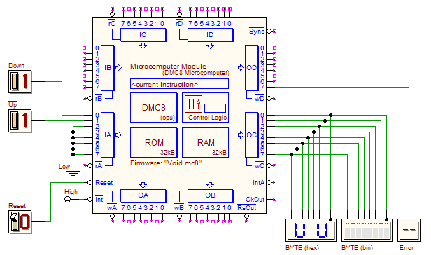
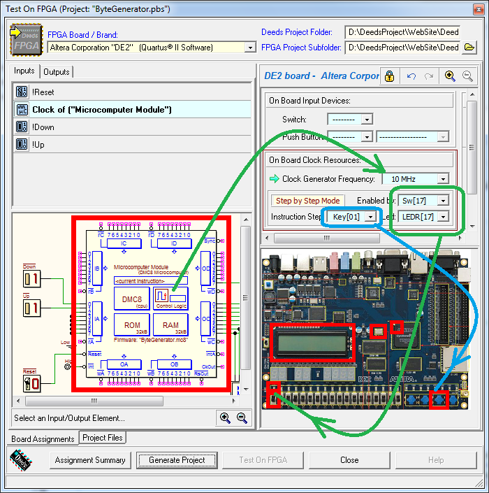
| In this laboratory, you will write and test the DMC8 assembly program that specializes a microcomputer system (represented in the figure below), to work as a byte generator, controlled by a couple of push-buttons. Once completed the design, you'll go to the physical implementation of the system on an Altera DE2 FPGA board. To open the schematic in the d-DcS, just click on the figure. The system includes a microcomputer (DMC8) and a few components connected to the parallel ports. In input, the microcomputer reads the !Down and !Up push-buttons (on IA port). On output, it generates the byte (on OC port), and a line reporting the Error condition (on bit 7 of OD port). To help the user in reading the current byte value, both binary and hex displays are used. Program specifications The program is executed at the system hardware !Reset. During the program initialization, the output lines must be cleared. Then, the processor enters a main, infinite, loop, in which it periodically reads the push-buttons, processes their state and, as a consequence, increments, decrements, or leaves unchanged the output byte (as described in the following). When !Down and !Up push-buttons are high (not pressed), the system maintains unchanged the output byte value. When the !Up push-button is pressed, the output byte value is incremented immediately by one and, if !Up is still pressed, it will be incremented again by one unit every 500 mS. If the byte value reaches the maximum, !Up activation will be ignored. In a similar way, when the !Down push-button is pressed, the output value is decremented immediately by one and, if !Down is still pressed, it will be decremented again by one unit every 500 mS. If the byte value reaches the minimum, !Down activation will be ignored. If !Down and !UP are activated at the same time, the system maintains unchanged the output value but activates the Error output line, which remains active until this anomalous input combination is removed. Suggestions and technical details Push-button "debouncing" A push-button is an electromechanical device. When it is pressed, or released, the electrical contacts, because of their inertia and elasticity, instead of a unique and clear transition, bounce between the two states. The bounces produce multiple and random commutations for a few milliseconds (depending on the device characteristics). We need to filter out these spurious transitions, otherwise we would send incorrect and multiple commands to the system: technically speaking, we need to "debounce" the push-button. A simple solution could be to compare the push-buttons state with the state read a certain time before (for instance, 25 mS). If the values are different, one or more of the push-buttons are in a transition state, i.e. during a pressing (or releasing) operation. If they result equal, the push-buttons state is stable and we can take it into account. The main loop To implement this method, the program main loop will execute, at every repetition, a 25 mS delay subroutine; then, the main loop reads the IA port current value, and saves it as the "previous value" that will be used on the next turn. If current and previous values do not match, the main loop simply repeats these operations, until the values match. In this case, it will continue decoding the state of each push-button, according to the specifications given before. Repeating commands every 500 mS Push-buttons control system operations in two situations: a) every time they are pressed, and b) when they remain pressed for more than 500 mS. This require that the program keeps account of the time elapsed. Each repetition of the main loop is executed every 25 mS (the time of execution of the delay subroutine), so the program needs simply to count the loop repetitions, starting from the last change of state of the push-buttons (500 mS = 25 mS x 20). The count needs to be cleared every time the push-buttons change (when pressed, released, or bouncing). When the buttons state is stable, the count is incremented (on every main loop repetition). Therefore, on the first occurrence when push-buttons are checked stable after a variation , the count goes to 1: this is the time to execute the required task (handling increments/decrements of the output byte). To repeat operations every 500 mS, we need to clear the count each time it reaches 20: on the next repetition of the main loop, the count will go to 1 again. In this way, we divide clearly the count operations from the task to be done: the condition needed to execute the task is simply that the count is 1, and so it will be execute a first time, when user presses the buttons and, after, every 500 mS. A suitable trace of the code, to be completed in the d-McE, is available here. We recommend to add comments to the source code in order to help its understanding. After completing the program, test its functionality in the d-McE debugger, and then load it in the microcomputer ROM, in the d-DcS schematic, to simulate the whole system with the timing simulator At this point we begin the procedure for the physical implementation of the project in the FPGA board. The general procedure is described in the introductory tutorials: The "Test on FPGA" command of the d-DcS will open the following dialog window:
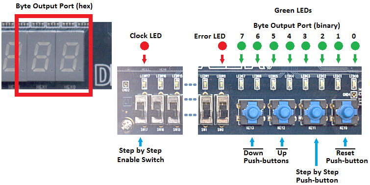
Note that all the needed associations between d-DcS schematic and the FPGA board input/outputs are already set in the given schematic: it is not necessary to modify them. The clock frequency is set to 10 MHz. The “Step by Step Mode” has been enabled, assigning to the switch Sw[17] the task to activate it at runtime. It has been selected a LED, LEDR[17], to visualize the clock pulses being sent to the microcomputer. Finally, the pushbutton Key[01] has been chosen to control the manual execution of the instructions. If Sw[17] is at '0', the debug system is not active and the microcomputer works with the "normal" clock (10 MHz). If Sw[17] is turned on at '1', the system stops clock generation and the debugger waits for the user to press Key[01] (each activation of the push-button executes one instruction). All defined associations are highlighted also in the next figure, useful for testing the physical system:
| |||||||||||


 . A proper test sequence is available in the timing simulation window. We recommend to avoid any change on the schematic about the input/output terminations, already defined for exporting the project on the FPGA board.

