|
|
||||||||||
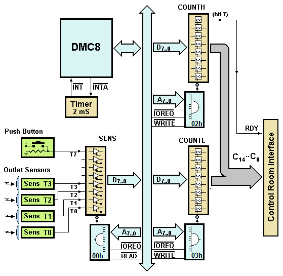
| A DMC8 microprocessor-based system counts the iron bolts produced by a semi-automatic press. A worker is in charge to load the press with the raw material and, when finished, to press a push-button to send to the control room the number of bolts produced (before to reload the machinery). The press has four separated outlets, controlled by independent sensors. Write and test the control program of the system (see the figure below), according to the following specification.
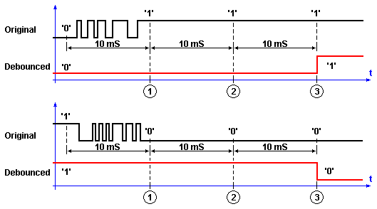
A timer, connected to the DMC8 processor, sends an interrupt request (!INT) every 2 mS: the interrupt acknowledge signal !INTA, generated by the processor during its interrupt start sequence, clears automatically the interrupt request. The parallel input port SENS (address 00h) reads the optical sensors T0, T1, T2 and T3 that control each press outlet. Each sensor generates ‘0’ in the idle state, and a ‘1’ when a bolt passes through its optical path. Also, a push button (the one that the worker will press) is connected to bit 7 of the same port. The control room is connected through a 16-bits parallel interface, that the system controls by the COUNTL and COUNTH port (address 03h and 02h). The interface uses a 15-bits parallel bus (C14..C0) to communicate the number of bolts, and a single line as the data-ready strobe (RDY). Firmware specification The microprocessor, in the main program, controls continuously the SENS port. It compares the previous and the current state of the sensors, detecting the ‘1’ to ‘0’ transitions of the sensors outputs and incrementing the total count of bolts. Suppose that the highest number of bolts produced is lower than about 10000. Let's also assume that the signal generated by the sensors is free from spurious transitions. The interrupt handling routine, executed at every “timer tick”, is in charge to control the push-button. An electro-mechanical button, when switched 'on' or 'off', produces a series of mechanical bounces that yield to a 'dirty' digital signal (with the presence of undesired 'pulse trains', as shown in the next figure). The switching needs to be cleaned and validated via software: in a word, it needs to be 'debounced'.
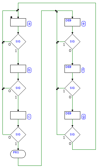
To do so, we'll sample the signal several times, and we'll validate its value only when it results stable consecutively more than one time. In the current example, we check the push-button value every 10 mS: we will accept a change only if the new value remains stable three times, i.e. at least for 20 mS, as shown in the previous figure. The debouncing algorithm can be described as a synchronous finite state machine (FSM, see the following figure), where each state transition is evaluated every 10 mS:
In the state diagram above, SIG is the signal from the push-button, and the output DEB follows it, but without bounces. The MSF remains in the state (a) if the push-button is idle (SIG = '0'). When a change to '1' of SIG is detected, SIG will be checked two more times [state (b) and (c)], every 10 mS. If, in the meantime, SIG returns to '0', the process of validation is restarted again, from state (a). If, in the state (c), the signal is read high again, we confirm the new value of the push-button (considering it "pressed") and the task associated with the button press is executed (in the diagram, this is represented by the conditional output PRS). Then, the FSM will continue to sample the signal every 10 mS, validating also the opposite transition, before restarting the entire process again, in the state (a). When the button is declared "pressed", the system sends the bolts number (C14..C0) to the control room, by copying it to the COUNTL and COUNTH ports and activating the RDY signal. RDY must be maintained active at least for 3 µS, and then cleared. Note that the RDY signal must be cleared without modify the C14..C0 lines. Here three templates are available for possible solutions, in assembly DMC8 code, in descending order of difficulty:
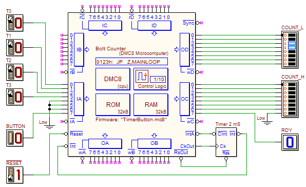
Who wants to deal only with the analysis of already written code, and the simulation of the system, will find here a complete solution. When finished to write and test the program in the d-McE, you would load it in the ROM of the microcomputer and simulate the whole circuit. Click on the next figure to open the schematic in the d-DcS. Note that, to test the receiver, the input "TestSequence" is available in the timing diagram window. | |||||||||||


