Deeds Demos (3)
Finite State Machines and Sequential Networks (Deeds-FsM, Deeds-DcS)
(click on the figure of interest to open the corresponding example)
Four States Binary Up Counter
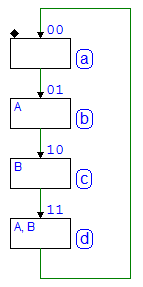
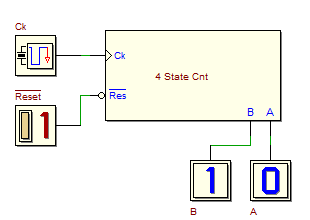
ASM state chart of a 4-states synchronous Finite State Machine, working as Binary Up Counter, designed with the Deeds-FsM, and the resulting component (in a Deeds-DcS schematic).
The Timing Diagram Simulation, executed in the Deeds-DcS:

Four States Up/Down Binary Counter
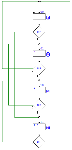
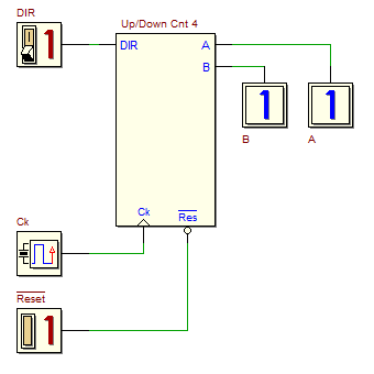
ASM state chart of another 4-states synchronous Finite State Machine, working as Binary Up/Down Counter, and the resulting component (inserted in a Deeds-DcS schematic). The input DIR defines the count direction ('1' = Up, '0' = Down).
Edge Detector (Moore and Mealy versions)
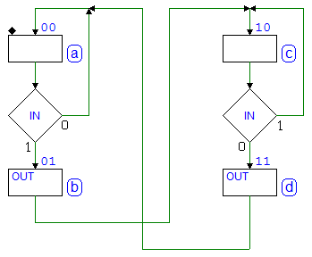
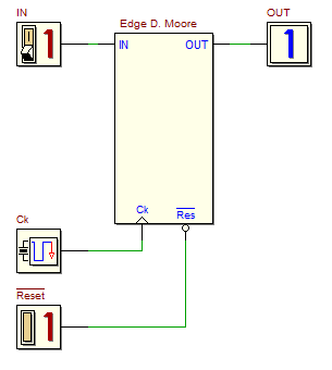
The first ASM state chart describes an Edge Detector as Moore Finite State Machine. Each time the input IN changes its value, it generates a pulse on the output OUT. The Edge Detector component , in the figure on the right side, has been inserted, to be tested, in a Deeds-DcS schematic.
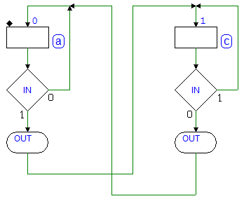
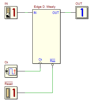
The second ASM state chart describes a similar Edge Detector, but designed as Mealy Finite State Machine:
The Timing of the two circuits are slightly different. Here the behavior of the Moore version, where the output OUT is synchronous with the clock:

In the next figure, instead, the behavior of the Mealy version, where the positive edge of OUT depends from the one of the input IN. The positive edge of OUT is not synchronous with the clock, nevertheless the circuit responds immediately to the changes of the IN signal, instead to wait the next clock edge (as in the Moore version).

Pulse Generator
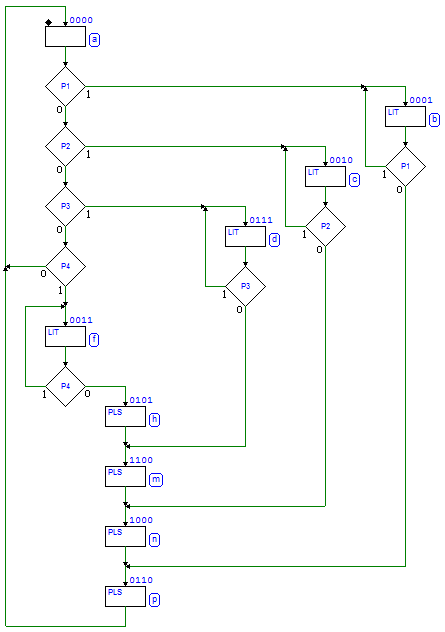
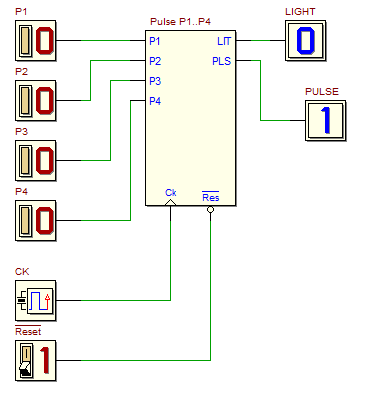
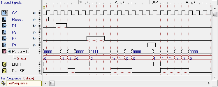
The Pulse Generator is described by the following ASM state chart: it generates pulses of different duration on the output PLS (PULSE). P1, P2, P3 and P4 are push-buttons: when one of these is pressed, the output LIT (LIGHT) is activated. Then, releasing the push-button, a pulse is generated on PLS. The pulse duration is 1, 2, 3, or 4 clock cycles if we press, respectively, P1, P2, P3 or P4.
Here an example of Timing Diagram Simulation of the pulse generator, in the Deeds-DcS:
Programmable Pulse Generator
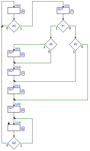
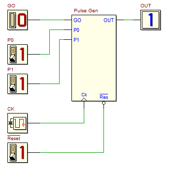
The following figure shows the ASM state chart of a Programmable Pulse Generator. On the positive edge of the input GO, the generator activates the output OUT, for a time duration equal to (2 + P1P0) clock cycles.
Here the Timing Diagram Simulation of the pulse generator, executed in the Deeds-DcS:

Retriggerable Pulse Generator
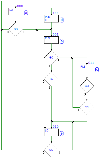
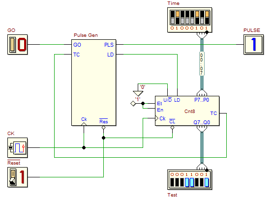
The following figures show the ASM state chart of a Retriggerable Pulse Generator, and the Deeds-DcS schematic of the circuit, that employs a 8-bits Universal Counter. On the rising edge of the input GO, the system activates the output PLS (PULSE), for a time T depending from the number set on the dip-switches Time. The generator is retriggerable: if a new rising edge of GO comes while a pulse is generated, its duration is extended by T.
Here a Timing Diagram Simulation example of the retriggerable pulse generator:

Light Dimmer
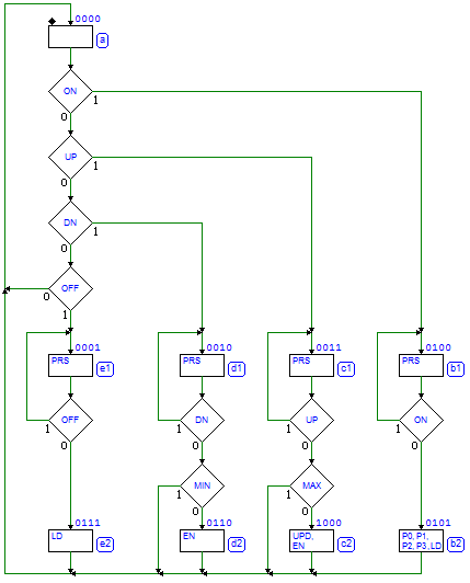
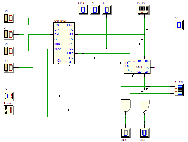
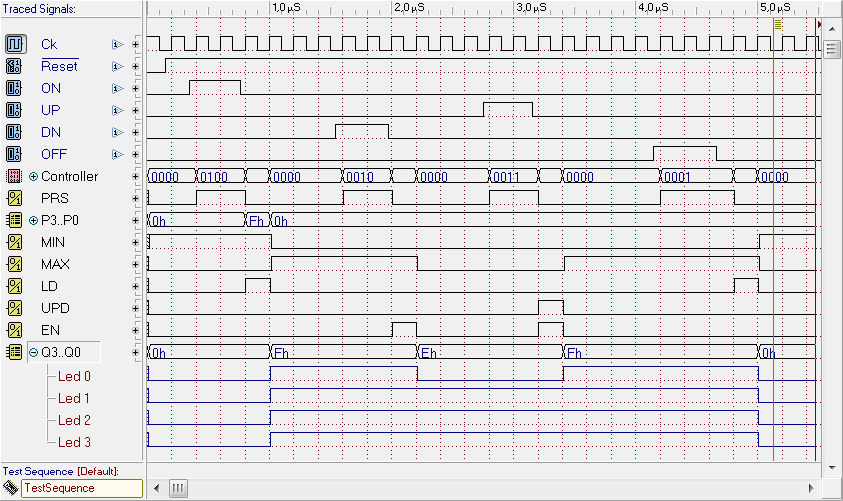
The following figures show the ASM state chart of a the Controller of a Light Dimmer, and the schematic that include, besides the Controller, a Universal 4-bits Counter and some glue logic. The Controller is in charge of Clear, Increment, Decrement and Maximize the counter output Q3..Q0, depending on the action of the user on one of four push-buttons, respectively OFF, UP, DN and ON. The counter output drives a LED lamp (not represented here). PRS is activated when a push-button is pressed, and the counter activity is controlled at the release of the button.
Here the Timing Diagram Simulation of the light dimmer, in the Deeds-DcS:
4-bits Asynchronous Serial Transmitter
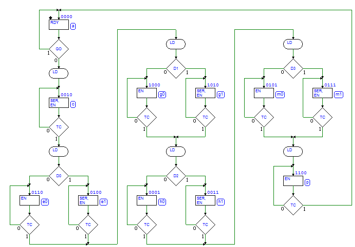
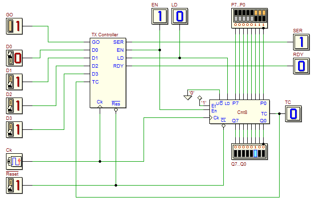
ASM state chart of the Controller, and schematic of a 4-bits Asynchronous Serial Transmitter
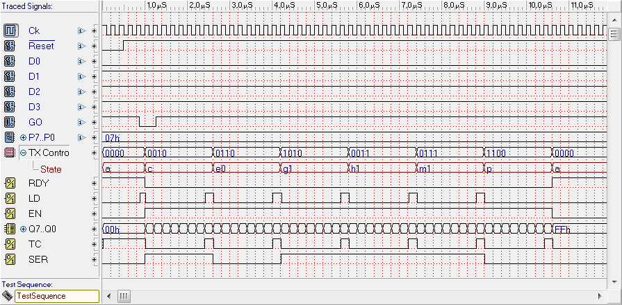
The circuit includes a Universal 8-bits Counter. The system generates, on the output SER, a six bits packet, composed of a start bit at '1', four data bits (D0, D1, D2 and D3), and a stop bit at ‘0’. The bit time duration, set by an 8-bit counter, is equal the number P7..P0 used to load it, plus one. A low level, on the GO input, commands the transmission of the packet. Waiting for GO, the controller activates RDY, signaling that it is ready to send a new packet. Here the Timing Diagram Simulation of the Serial Transmitter:
