Deeds Demos (4)
Microcomputers, Assembly Programming and Embedded Systems(Deeds-McE, Deeds-DcS)
(click on the figure of interest to open the corresponding example)
Simple Input/Output Program
The following figure shows an assembly program in the source code editor of the Deeds-McE (click on the figure to open the shown program in the tool. The main loop reads cyclically the data on the port INPORT and copies it to the port OUTPORT. Note that the DMC8 assembly language is compatible with that of the Z80 microprocessor.
Click here for a synthetic DMC8 reference.

After having compiled the program, and then loaded it into the emulated system memory of the Deeds-MCE, you'll test it in the debugger. There are some specialized panels for displaying Internal Register contents, Memory (ROM and RAM), In/Out Ports and the Object Code to be executed: you can run the programs in Animation or Step-by-Step mode.

See the following figure: we included in the schematic a DMC8 Microcomputer component and some Input and Output devices (click on the figure to test youself the circuit).
The program has been loaded in the ROM of the microcomputer. Note that, with the Deeds-DcS, you can test the whole system, not just emulate the program only.

 (you can set the animation speed using the slider available on the tool bar).
With the context menu of the microcomputer component, you can open the debugger windows. See below an example of the Object Code window, where the current instruction is highlighted.

In this window, the "Instruction Step" button lets you execute the program step-by-step. However, this button is visible only if you stop the clock pulsing (un-check the button near the animation speed slider). When the "Instruction Step" button is pressed, the current instruction is executed, and the highlighting is moved to the next one.
Delay loops
This program executes an infinite loop. In it, cyclically, some LEDs are switched On and Off. The LEDs are connected to the Output Port (address 00h). You can click on the figure to test the program.
The LEDs stay Off for 200 mS, and On for 800 mS (approx.). To evaluate the elapsed time, the program calls the subroutine DELAY, to which passes the desired delay value (in mS) through the register HL.

In the following figure you see the debugger in action: inserting breakpoints appropriately, you can measure the delay (as number of clock cycles), by means of the two clock cycle counters in the tool bar. Use the Clear button to reset the partial counter when needed.

Instruction Set List
A click on the figure below will open, in the Deeds-McE, a source file including all the available DMC8 instructions. The DMC8 assembly language instructions are a subset of those of the Z80 microprocessor.

Assembler Directives: EQU, ORG, DB and DW
Click on the next figure: you'll see a few examples of the EQU, ORG, DB and DW directives:
 s
sEQU (Equal) is used to define constants (data, addresses).
ORG (Origin) controls the allocation address of the following instruction (EQU and ORG do not generate executable code).
DB (Define Byte) and DW (Define Word), instead, are used to generate constant data to be permanently stored in ROM.
The examples in the source code above explain various modes of using the directives; the figure below, instead, reports the results, in memory, of the compilation of the same code (highlighted in color):

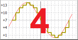
"Wave Table" Sequence Generator
This program produces, on the output port WaveOut, a cyclic sequence. A click on the figures below will open, in the Deeds-McE, the source file:

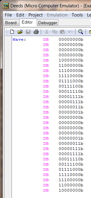
Note that it uses an Interrupt technique to read from a table, in a regular way, the bytes to be generated. The sequence is defined in the table "Wave", using the DB directive:
The system includes a Cyclic Interrupt Timer (programmed at 0.1 mS), as visible in the next figure. Click on the figure to open the schematic in the Deeds-DcS, ready to be simulated:

By adjusting the frequency of the animated clock to about 10 KHz, and enabling the clock animation (see figure below), we can observe the behavior of the generator, in a realistic way, using the Interactive Circuit Animation:

A timing analysis is more precise: we can study the behavior of the system with the timing simulation. As you can see in the figure below, in the Timing Diagram window we can also enlarge a portion of the simulation. In this example, in the magnified area (in yellow), we can see the particulars of the processor response to the Interrupt request:

If we activate the "Value Cursor" (see the following figure), placing it on the track "Wave Table" of the microcomputer, we are able to analyze the program instructions, in execution order. In this example, you can see a tracing the interrupt routine: