|
|
||||||||||
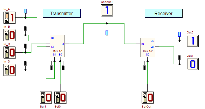
| In this exercise you will test the simplified shared-line communication channel, represented in the figure below. The left side of the schematic represents the Transmitter, the right side the Receiver. The transmitter selects one of the four inputs (In_A, In_B, In_C and In_D) and transmits it to the Channel (note that only one signal at a time can be transmitted). The Channel, at the receiver side, will be routed to one of the two outputs (Out0 and Out1). Click on the figure to open in the d-DcS a trace of the network's schematic, and then complete it to obtain the schematic below. The "Mux 4-1" and "Demux 1-2" components are available on the component toolbar of the d-DcS. Once completed the schematic, start the functional
simulation of the network
| |||||||||||


 , and then the timing simulation
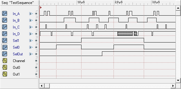
  . The test sequence shown below is available in the Timing Diagram window: in this sequence, inputs change their values in a way that make easy to identified their variations throught the line Channel and the outputs Out0 and Out1, according to the values of the control inputs Sel0, Sel1 and SelOut.