|
|
||||||||||
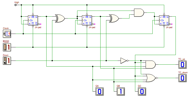
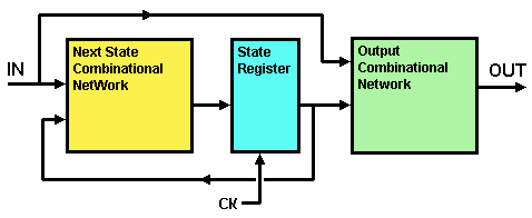
| The following network is a Synchronous Up/Down Binary Counter (click on the figure to open it in the d-DcS): In the schematic, the counter outputs are: QA, QB, QC. The input Down sets the direction of the count (up = '0', down = '1'). The output TC_up (Terminal Count, 'Up' direction) is activated to '1' when the up count reaches the maximum number ['111']; instead, the output TC_down (Terminal Count, 'Down' direction) is activated when the down count reaches zero ['000']. Verify such behaviour with the timing simulator Now you should review the network schematic, re-thinking it as Finite State Machine (FSM). Consider the Mealy Synchronous FSM model (see next figure):
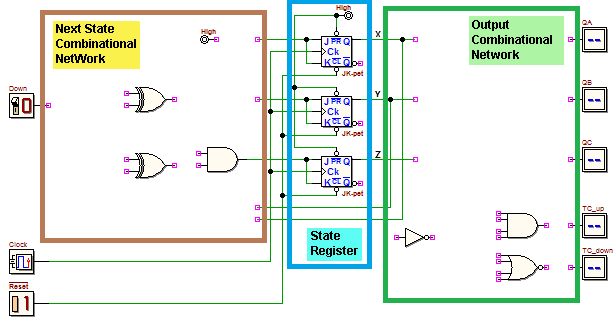
Now you had to re-group the same network in a new schematic, where the components are placed accordingly to the functional blocks defined by the model (click on the figure and complete the schematic in the d-DcS): In the new schematic, we define three state variables X, Y and Z (the outputs of the flip-flops QA, QB and QC, in the original schematic). Verify the behaviour of the re-grouped network with the timing simulator of the d-DcS | |||||||||||


 (a suitable test sequence is available in the Timing Diagram window).
