Introduction to Sequential Networks
5.1 From Combinational Networks to Sequential Networks
5.1.1 Introductory Example

5.1.2 Memorizing an Information Bit: Flip-Flops
One-bit memory cell

Transforming the one-bit memory cell into a Set-Reset flip-flop


5.2 Direct Command Flip-Flops
5.2.1 SR Flip-flop
SR Flip-flop (active-high commands, NAND version)

SR Flip-Flop (active-low commands, NAND version)

SR Flip-Flop (active-high commands, NOR version)

5.2.2 D Flip-flop
Degenerate (useless) version

5.2.3 JK Flip-flop
Version without initialization, not simulable

5.3 Initialization of a Sequential Network
5.3.1 Flip-flop Initialization Inputs
JK Flip-flop with Clear input

JK Flip-flop with Clear and Preset inputs

5.4 Level-Enabled Flip-Flops
5.4.1 SR-Latch Flip-flop SR

5.4.2 D-Latch Flip-flop)

5.4.3 JK-Latch Flip-flop

5.5 Synchronization of Sequential Networks
5.5.2 Pulse Command in Level-Enabled Flip-Flops

5.5.4 Master-slave Structure

5.6 Edge-Triggered Flip-Flops
5.6.1 D-PET Flip-flop
Basic structure

Typical structure

Typical structure with initialization inputs

D-PET Flip-flop

5.6.2 E-PET Flip-Flop
Preliminary wrong version, with synchronization problems

Correct version

E-PET Flip-Flop symbol

5.6.3 JK-PET Flip-Flop
JK-PET function, obtained with a D-PET type flip-flop

JK-PET Flip-flop Symbol

5.6.4 T-PET Flip-flop
T-PET function, obtained with a JK-PET type flip-flop

T-PET function, obtained with a D-PET type flip-flop

T-PET function, obtained with an E-PET type flip-flop

5.6.5 Synchronous Initialization of Flip-Flops
D-PET Flip-flop with synchronous clear
![]()
E-PET Flip-flop with synchronous clear (not in the book)

5.9 Exercises
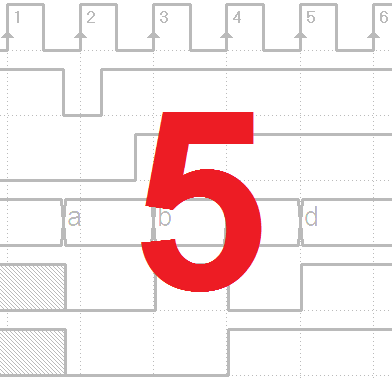
Print the PDF files with the timing diagrams (click on the figure of interest). The time diagrams are the same that appear in the book. They must be completed without the aid of the simulator.
Exercises 1 and 2:

Exercises 3 and 4:

Exercises 5 and 6:

5.10 Solutions
The solutions must be verified in the simulator Timing Diagram. In each file (click on the inherent figure) the input sequence is already defined. It will be automatically loaded when opening the Timing Diagram window.
Exercise 1:

Exercise 2:

Exercise 3:

Exercise 4:

Exercise 5:

Exercise 6: