Sequential Networks as Finite State Machines
7.1 Finite State Machines: Standard Model
7.1.3 An Example of Synchronous Finite State Machine
Example of Synchronous Network

Schematic of the same network, redrawn according to the general model of Synchronous Moore MSF:

7.2 ASM Diagrams
7.2.1 Description of States

7.2.2 Inputs
Variable Module Counter

Up/Down Binary Counter

Edge Detector: first version (four states)

7.2.3 Conditional Outputs

Edge Detector: second version (two states with Conditional Outputs)

Edge Detector: third version (four states with Conditional Outputs)

7.3 Examples of ASM Diagram Construction
7.3.1 Introductory Examples
Example 1

Example 2

Example 3

Example 4

Example 5

Example 6

Example 7

Example 8

Example 9

Example 10

Example 11 (Moore and Mealy versions) .


Example 12

7.3.2 Example
First and second version


Third version

7.3.3 Sequence Detector

7.3.4 Serial Synchronous Transmitters (2 bits)

7.3.5 Command Receiver with Serial Synchronous Interface

7.3.6 Serial Synchronous Receiver (2 bits)

7.3.7 Push-Button Handling

7.3.8 3-Bit Shift Registers

Network behavior as FSM

7.3.9 3-Bit Shift Registers

Network behavior as FSM

7.3.10 Shift Register with XOR Tree

Network behavior as FSM

7.4 Synthesis of Synchronous FSM
7.4.2 Describing an FSM with a State Table
Example of FSM

7.4.3 State Table Synthesis
Next State and Outputs Combinational Networks


7.4.4 Examples of Synchronous FSM Synthesis
Example 1 (2-Bit Up/down Counter). ASM diagram and logical schematic of the resulting network


Example 2 (Up/down Counter with Maximum and Minimum Outputs). ASM diagram and logical schematic of the resulting network using D-PET flip-flops


ASM diagram and logical schematic of the resulting network using JK-PET flip-flops

Example 3 (Sequence Detector). ASM diagram and logical schematic of the resulting network


Example 4 (Push-Button Handling): ASM diagram

Example 4: logical schematic of the resulting network

7.6 Exercises
7.6.1 Sequential Network Analysis in Terms of FSMs
A click on the FSM component symbol, shown on the right of each schematic, will open a template of the ASM diagram in the Deeds-FsM .
A click on the schematic, instead, will open in the Deeds-Dcs a network that will allow you to compare, adding your FSM, the behavior of the given network with your solution.
Network 1


Network 2


Network 3


Network 4


Network 5


Network 6


Network 7


Network 8


7.6.2 FSM Design Based on Textual Specifications
A click on the component symbol, shown on the left, will open in the Deeds-FsM a template of the FSM to be designed, where the state variables, the inputs and the outputs are already defined.
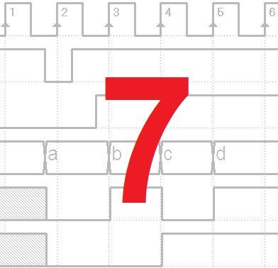
Once completed the ASM diagram, print the PDF file with the timing diagram (click on the figure in the middle). The timing diagram is the same that appears on the book under the exercise assignment. It must be completed on paper without the aid of the simulator.
Finally, with a click on the schematic on the right, you will open in the Deeds-Dcs the network to be completed with your FSM, to complete the analysis of its behavior using timing simulation.
Exercise 1


Exercise 2


Exercise 3


Exercise 4


Exercise 5


Exercise 6


Exercise 7


Exercise 8


7.7 Solutions
7.7.1 Sequential Network Analysis in Terms of FSMs
ASM diagram of network 1

ASM diagram of network 2

ASM diagram of network 3

ASM diagram of network 4

ASM diagram of network 5

ASM diagram of network 6

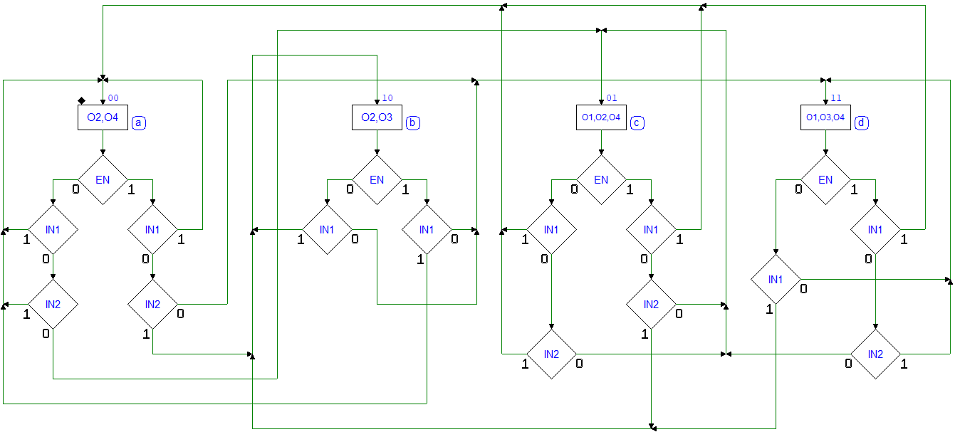
ASM diagram of network 7

ASM diagram of network 8

7.7.2 FSM Design Based on Textual Specifications
Click on the diagram on the left to open the solution in the Deeds-FsM . With a click on the schematic on the right, instead, you will open the network in the Deeds-DcS to check its behavior with the timing simulation.
Exercise 1

Exercise 2

Exercise 3

Exercise 4

Exercise 5

Exercise 6

Exercise 7

Exercise 8

7. Errata Corrige (Chapter 7)
Page 276
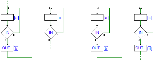
First figure, on top of the page. The decision block on the left has been corrected:
Pag. 353
Network 7 solution has been corrected: