The Finite State Machine as System Controller
8.2 Open Control Systems
8.2.1 2-Bit Serial Receiver
FSM only version


FSM + datapath version (two E-PET flip-flops)


8.3 Feedback Control Systems
8.3.1 2-Bit Serial Receiver and Transmitter


8.3.2 Pulse Generator
FSM only version


"Cnt4" Counter, ready to be simulated

FSM + datapath version (with the "Cnt4" counter)


Version with extended time measurement (16-bit)

8.3.3 8-Bit Serial Receiver
"Sipo8" shift register, ready to be simulated

FSM + datapath version (with the "Sipo8" shift register)


Version counting the number of bits (using a "Cnt4")


8.3.4 Light Dimmer
Network schematic

Controller algorithm

8.3.5 Combination Lock
Network schematic

Controller algorithm

8.3.6 Automatic Drink Dispenser
Network schematic

Controller algorithm

8.3.7 Programmable Square Wave Generator
Network schematic

Controller algorithm

8.3.8 Christmas Light Systems
Network schematic

Controller algorithm

8.4 Design Exercises
8.4.1 Design of the Controller of a Given Datapath
A click on the component symbol, shown on the left, will open in the Deeds-FsM a template of the FSM to be designed, where the state variables, the inputs and the outputs are already defined.
Once completed the ASM diagram, print the PDF file with the timing diagram (click on the figure in the middle). The timing diagram is the same that appears on the book under the exercise assignment. It must be completed on paper without the aid of the simulator.
Finally, with a click on the schematic on the right, you will open in the Deeds-Dcs the network to be completed with your FSM, to complete the analysis of its behavior using timing simulation.
Exercise 1


Exercise 2


Exercise 3


Exercise 4


Exercise 5


Exercise 6


Exercise 7


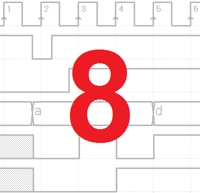
Exercise 8


Exercise 9


8.6 Solutions
8.6.1 Design of the Controller of a Given Datapath
A click on the ASM diagram on the left will open the solution in the Deeds-FsM . With a click on the schematic, on the right, you will open the complete network in the Deeds-Dcs. We suggest to verify its behavior using timing simulation.
Exercise 1

Exercise 2

Exercise 3

Exercise 4

Exercise 5

Exercise 6

Exercise 7

Exercise 8

Exercise 9

8.6.2 Design of a Controller–Datapath System
A click on the schematic, on the left, you will open the complete FSM + datapath network in the Deeds-Dcs. A click on the ASM diagram on the right will open it in the Deeds-FsM . We suggest to verify its behavior using timing simulation.
Exercise 1


Exercise 2


Exercise 3


Exercise 4


Exercise 5


Exercise 6 (no controller is needed)

Exercise 7