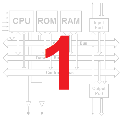
Introduction to programmable computing networks
1.2 Design of a programmable computing network
1.2.1 The design specification: a dedicated computing network
1.2.1.1 Combinational solution

1.2.1.2 Sequential solution


1.2.1.3 The state chart of the sequencer

1.2.2 Counter and ROM memory based sequencer


1.2.3 Extending computing possibilities
ALU

ALU test

1.2.4 ALU-based computing networks
The network has been called Mp8A and is also available in Appendix B of the book.

To program the program memory with the 'average calculation' example reported below (and described in the book), you can use the file available here.
1.3 Sequencing, microinstructions and microprograms
1.3.1 A more compact sequencer

1.3.2 The microprogrammed sequencer

1.3.3 The microprogrammed sequencer and the computing network
This network has been named Mp8B and is also reported in Appendix B of the book.

To program the program memory with the 'average calculation' example described in the book and also shown below, you can use the file available here.
1.4 Jumps, loops and decisions
1.4.1 Loops and jump instructions
The network supporting unconditioned jumps.
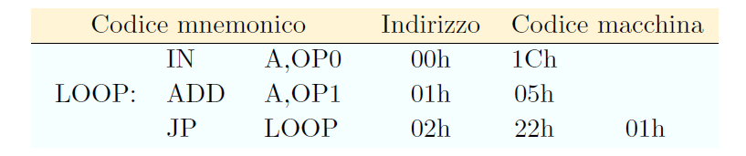
The figure below is partial, showing only the changes to the sequencer with respect to the previous network (explained in the book). With a click on the figure, the complete network will open in Deeds, already programmed with the introductory example described in the book and reported after the figure.

1.4.2 Decisions and conditional jump instructions
The network supporting conditioned jumps.
The next two figures represent the changes compared to the previous Mp8B network (the FLAG register and the jump condition control network). With a click on the figures, the complete network (Mp8C) will open in Deeds, capable of performing conditional and unconditional jumps.


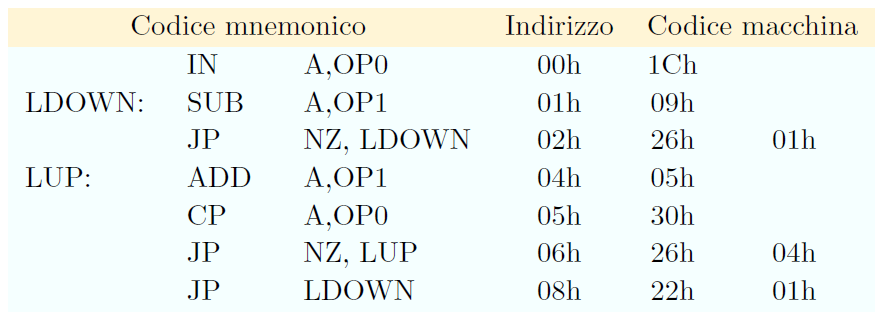
To program the program memory with the example on conditional jumps described in the book and also reported below, you can use the file available here.
1.5 Input and output ports
The two figures in the book represent the input and output ports, the latter added to the previous network (Mp8C) . With a click on the figure, the complete network will open in Deeds (Mp8D).


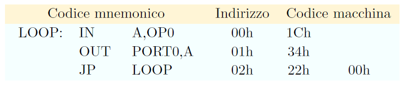
To program the program memory with the introductory example on the input and output ports, also shown below, you can use the file available here.
1.5.3 How to use ports
For each example, the ROM programming file (program memory) is provided, together with the appropriate network to use. For the first two examples, DAC (Digital to Analog Converter) components have been added to the Mp8D network, useful to display the sequence of port outputs. Note that the DACs display signed numbers (two's complement coded), with a range between -128 and +127.
It is recommended to set the constants on the input ports as suggested for each example.
1.5.3.1 Generating a periodic triangular waveform
- Network Mp8D (with the addition of DACs)
- Program
- OP0 = 7Fh (starting value assumed greater than zero)
- OP1 = 01h (for the increment of 1)
- Clock animation frequency = approximately 300 Hz
1.5.3.2 Generating a periodic trapezoidal waveform
- Network Mp8D (with the addition of DACs)
- Program
- OP0 = 01h (for the increment of 1)
- OP1 = 20h (starting value assumed greater than zero)
- OP2 = 60h (end value assumed greater than OP1 and greater than zero)
- OP3 = 1Fh (duration of the pause assumed greater than zero)
- Clock animation frequency = approximately 300 Hz
1.5.3.3 Generating signals with the PWM technique
- Network Mp8D
- Program
- OP0 = 00h (to clear the accumulator, after the port initialization)
- OP1 = 3Fh (PORT0 test)
- OP2 = 7Fh (PORT1 test)
- OP3 = 01h (increment of 1, but also initialization to 1 of the lines 0 of the ports)
- Clock animation frequency = approximately 300 Hz
1.6 Constants, variables and read/write memory
After adding the ability to read constants from program memory, and adding RAM memory, the final processor network is the following one (Mp8E):

1.6.8 Use of the Mp8E network: examples
For each example the ROM programming file (program memory) is provided, together with the appropriate network to use. In the third example, DAC (Digital to Analog Converter) components have been added to the Mp8E network, useful to display the sequence on port outputs. Remember that the DACs display signed numbers (two's complement coded), with a range between -128 and +127.
It is recommended to set the constants on the input ports as suggested for each example.
1.6.8.1 Calculating a logical expression
- Network Mp8E
- Program
- Hint: OP0 = 11h
- Hint: OP1 = 10h
- Clock animation frequency < 5 Hz, or animation disabled
1.6.8.2 Calculation of a mathematical expression
- Network Mp8E
- Program
- Hint: OP0 = D8h
- Hint: OP1 = 03h
- Clock animation frequency = 20 Hz, or animation disabled
1.6.8.3 Generating the samples of a sinusoidal wave
- Network Mp8E (with the addition of DACs)
- Program
- OP0, OP1: not used
- Clock animation frequency = 30 Hz, or animation disabled
1.7 Exercises
1.7.1 Dedicated computing networks
Exercise 1 (template):

Exercise 2 (template):

Exercise 3 (template):

Exercise 4a (templates of the computing network and the FSM):


Exercise 4b (templates of the computing network and the FSM):


Exercise 5a (template):

Exercise 5b (template):

Exercise 6 (templates of the ALU and the test network):


Exercise 7 (templates of the comparator and the test network):


1.7.2 Programmable computing networks
Exercises 1a, 1b, 1c:
(Mp8A computing network, to be programmed)

Exercises 2a, 2b:
(Mp8C computing network, to be programmed, where a DAC has been added to allow to display the generated waveforms. Note that the DAC displays signed numbers [two's complement coded], with a range between -128 and +127)

Exercises 3a, 3b:
(Mp8D computing network, to be programmed, where two DAC have been added, to allow to display the generated waveforms. Note that the DAC displays signed numbers [two's complement coded], with a range between -128 and +127)

Exercises 4, 5, 6, 7:
(Mp8E computing network, to be programmed)
1.8 Solutions
1.8.1 Dedicated computing networks
Exercise 1:

Exercise 2:

Exercise 3:

Exercise 4a (computing network and FSM):


Exercise 4b (computing network and FSM):


Exercise 5a (computing network and ROM programming file):


Exercise 5b (computing network and ROM programming file):


Exercise 6 (modified ALU and test network):


Exercise 7 (comparator and test network):


1.8.2 Programmable computing networks
The ROM (program memory) programming files can be downloaded below (preceded by the link to download the file of the relative network to be programmed).
Mp8A network:
Exercise 1a,
Exercise 1b,
Exercise 1c
Mp8C network:
Exercise 2a,
Exercise 2b
Mp8D network:
Exercise 3a,
Exercise 3b
Mp8E network:
Exercise 4,
Exercise 5,
Exercise 6,
Exercise 7
1.8.3 Microprogramming new instructions
Overall solution of exercises 1, 2, 3, 4, 5, 6, 7, 8: Programming file (of the microprogram memory) Mp8E network (to be re-programmed)
1. Errata Corrige (Chapter 1)
None