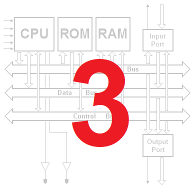
Programming the DMC8
3.1 Introduction to assembly language programming
3.1.6 The DB and DW directives
A click on the example will open the assembly code in the Deeds-McE:

3.2 Addressing modes
3.2.4 REGISTER INDIRECT addressing mode
3.3 Types of instructions
3.3.2 Arithmetic and logic instructions
3.3.2.1 Arithmetic instructions (8-bit data)
 The use of ADD and ADC with indirect addressing, an example
Examples of how the CP instruction is used
3.3.2.2 16-bit arithmetic instructions
Example of a 16-bit addition using HL
Example of a 64-bit adding algorithm
3.3.2.3 Logic instructions
Example of the use of the AND instruction (1)
Example of the use of the AND instruction (2)
Example of the use of the XOR instruction
3.3.2.5 Increment and decrement instructions (16-bit)
Example of the use of the DEC instruction (8-bit)
Example of the use of the DEC instruction (16-bit)
3.3.3 Rotate and shift instructions
The use of the RLC instruction: An example
Example of the use of the SLA and RL instructions
3.3.4 Bit manipulation instructions
The use of the BIT and RES instructions: An example
3.3.5 Jump instructions
3.3.5.1 Unconditional jumps
3.3.5.3 Indirect jumps
Jump tables (example of the use of the indirect jumps
3.3.5.4 Delay loops
Example of delay loop using a 8-bit counter
Example of delay loop using nested loops
Delay loops with 16-bit counter
Checking delay times in the emulator
3.3.7 Input/output instructions
Example of the use of the IN and OUT instructions (1)
Example of the use of the IN and OUT instructions (2)
3.5 Programming examples
3.5.1 Emulation of combinational logic
A click on the schematic on the left will open the example of a logic network to emulate in the Deeds-DcS. In the center, a click on the icon allows you to open the program that emulates the logic network in the Deeds-McE. By clicking on the diagram on the right, it is possible to open a microprocessor system in the Deeds-Dcs, programmed with that program, ready to verify its behavior through simulation.
3.5.1.1 The NOT gate:
|
|
|
|


3.5.1.2 The two-input AND gate
Example 1:
|
|
|
|


Example 2:
|
|
|
|
Example 3:
|
|
|
|

3.5.1.3 The two-input multiplexer
Example 1:
|
|
|
|


Example 2:
|
|
|
|
3.5.1.4 The 3-8 decoder
Example 1:
|
|
|
|


Example 2:
|
|
|
|
Example 3:
|
|
|
|
Example 4:
|
|
|
|
3.5.2 Calculating a polynomial
A click on the icon on the left allows you to open the program described in the text in the Deeds-McE. By clicking on the schematic on the right, it is possible to open a microprocessor system in the Deeds-DcS, programmed with that program, ready to verify its behavior through simulation.
|
|
|

3.5.3 Timers
|
|
|

3.5.4 Finite state machines
|
|
|

3.6 Exercises
3.6.1 Emulation of digital components
A click on the schematic on the left will open the example of a logic network to emulate in the Deeds-DcS. In the center, a click on the icon allows you to open a trace of the program to be written in the Deeds-McE. Finally, by clicking on the diagram on the right, it is possible to open a microprocessor system in the Deeds-Dcs, ready to load the program to be tested. It will be useful to verify its behavior using simulation by animation and then in the timing diagram window. When applicable, a test sequence is already set up in the timing diagram window and will be loaded automatically.
Note: where the assigned component is synchronized by a clock, it is suggested to limit the frequency of this to a value no greater than 10 KHz (the component emulated by software will be physiologically slower than the real component). The animation speed of the clock has already been conveniently set.
Exercise 1:
|
|
|
|


Exercise 2:
|
|
|
|


Exercise 3:
|
|
|
|


Exercise 4:
|
|
|
|


Exercise 5:
|
|
|
|


Exercise 6:
|
|
|
|


Exercise 7:
|
|
|
|


Exercise 8:
|
|
|
|


Exercise 9:
|
|
|
|

3.6.2 Arithmetic functions
A click on the icon shown on the left will open a trace of the program to be completed in the Deeds-McE. Finally, by clicking on the diagram on the right, when present, it is possible to open in the Deeds-DcS a microprocessor system ready to be loaded with the program to test. It will be useful to verify its behavior through simulation.
Exercise 1 (first trace):
|
|
|
Exercise 1 (second trace):
With this version of the caller it is possible to calculate the average between the two 32-bit numbers (A31..A0 and B31..B0) set on the input ports and display it on the output ports (this version is not present in the book).
|
|
|

Exercise 2:
|
|
|

Exercise 3:
|
|
|

Exercise 4:
|
|
|

3.6.3 Reusable modules and functions
A click on the icon shown on the left will open a trace of the program to be completed in the Deeds-McE. Finally, by clicking on the diagram on the right, when present, it is possible to open in the Deeds-DcS a microprocessor system ready to be loaded with the program to be tested. It will be useful for testing its behavior through simulation.
Exercise 1:
|
|
|
Exercise 2:
|
|
|

Exercise 3:
|
|
|

With the following version of the network it is possible to animate the LED column thanks to a counter. The assembly code is the same before (this solution is not presented in the book):
|
|
|

Exercise 4:
|
|
|

Exercise 5a:
|
|
|

Exercise 5b:
|
|
|

Exercise 6:
|
|
|

3.7 Solutions
3.7.1 Emulation of digital components
A click on the icon on the left allows you to open the program described in the text in the Deeds-McE. By clicking on the schematic on the right, it is possible to open the microprocessor system in the Deeds-Dcs with the same program already set up to simulate its behavior.
Solution of exercise 1:
|
|
|
Solution of exercise 2:
|
|
|
Solution of exercise 3 (first version):
|
|
|
Solution of exercise 3 (second version):
|
|
|
Solution of exercise 4:
|
|
|
Solution of exercise 5:
|
|
|
Solution of exercise 6:
|
|
|
Solution of exercise 7:
|
|
|
Solution of exercise 8:
|
|
|
Solution of exercise 9:
|
|
|
3.7.2 Arithmetic functions
A click on the icon on the left allows you to open the solution described in the text in the Deeds-McE. By clicking on the schematic on the right, when present, it is possible to open the microprocessor system in the Deeds-Dcs with the same program already set up to simulate its behavior.
Solution of exercise 1 (first version):
|
|
|
Solution of exercise 1 (second version):
With this version of the caller it is possible to calculate the average between the two 32-bit numbers (A31..A0 and B31..B0) set on the entry ports and display it on the exit ports (this solution is not present in the book).
|
|
|
Solution of exercise 2:
|
|
|
Solution of exercise 3:
|
|
|
Solution of exercise 4 (first version):
|
|
|
Solution of exercise 4 (second version):
|
|
|
3.7.3 Reusable modules and functions
A click on the icon on the left allows you to open the solution described in the text in the Deeds-McE. By clicking on the schematic on the right, when present, it is possible to open the microprocessor system in the Deeds-Dcs with the same program already set up to simulate its behavior.
Solution of exercise 1:
|
|
|
Solution of exercise 2:
|
|
|
Solution of exercise 3:
|
|
|
With the following version of the network it is possible to animate the LED column, thanks to a counter, without changing the assembly code (this solution is not presented in the book):
|
|
|
Solution of exercise 4:
|
|
|
Solution of exercise 5b:
|
|
|
Solution of exercise 6:
|
|
|
3. Errata Corrige (Chapter 3)
None