Version Notes
(Ver. 1.92.200 - March 27, 2015)
 Deeds-DcS (Component Library, Schematic Editor)
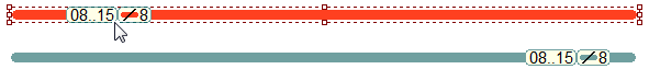
 New components have been added to the library and, starting with the present version, you can use Bus Connections to join them. As you see in the figure below, a Bus is equivalent to a group of wires, and is represented as a thick colored line
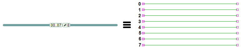
The number of wires that a Bus groups together is the "Bus Size" (ranging from 4 to 64). The wires are indexed: in the example above, the bus is composed of 8 wires, indexed from 0 to 7.
We introduced also a new type of pin ("Bus Pin"), designed to connect a component directly to a Bus (see the next figure). Its shape reminds that the Bus actually separates into wires, connected to the component. We use Bus Pins to make the schematics more concise and readable
In the next figure, you see some example of Bus, Tap, Splitter and Wire Connections:
See below the Bus Connections menu:
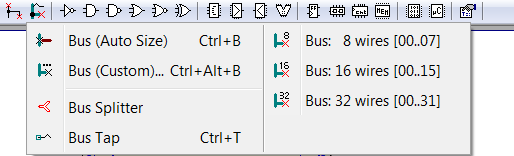
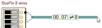
The command "Bus (Auto Size)" allows tocreate a Bus starting with a click on aBus Pin: the new Bus will get itsBus Size property directly from the Bus Pin.
In the example below, the bus acquires the size of 8 from the Bus Pin of the Input Dip-Switches. By default, the index range of a newly created bus is zero-based (00..07 in this example).
To connect buses of different size, you need a Bus Splitter, as in the following example, where a bus of 16 wires is splitted in two parts (not necessarily of equal size):

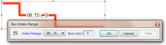
The Bus Splitter is only a "connector", the index range of the buses around the splitter is a property of each connected bus section, not of the Bus Splitter. With the bus context menu, you can open the Bus Index Range dialog and change the Index Range property of a bus section, as needed:
The Bus Label can be displayed for each bus segment, using the Bus Label Visibility dialog, available through the bus context menu:
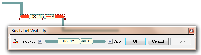
Moreover, the Bus Label can be dragged along the bus segment:
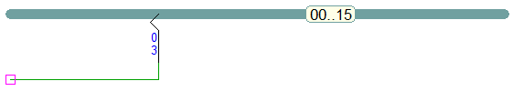
To connect a Wire to a Bus, you need a Tap. The figure below shows a single wire joined to the wire of index 03 of the bus:
To connect a component without bus pins, you can insert all the taps and wires needed in a few steps, described by the following figures:
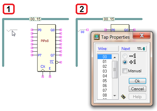
1) Position a Tap, aligned with the first of contiguous pins of the component; 2) After inserting the first Tap, the Tap Properties dialog is displayed, to choose the initial wire index and the direction of the increment;
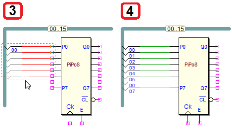
3) When the dialog is closed with OK, a group of Taps and Wires will show up, following the mouse movement; 4) With a mouse click the insertion operations will end.
The new library includes many new elements, including
components with Bus Pins, arithmetic circuits, memories, and more. Below, a few examples from the new library.
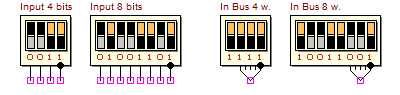
Input Components (4-bits and 8 bits [Wire and Bus version]):
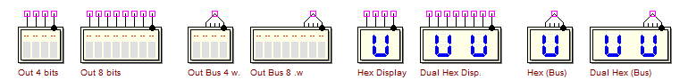
Output Components (4-bits and 8 bits [Wire and Bus version]):
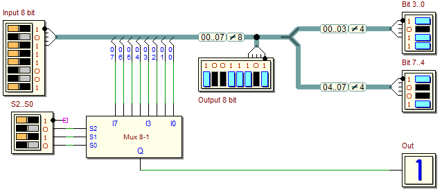
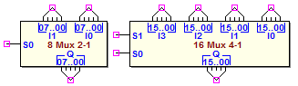
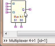
Bus multiplexers (2 to 1 and 4 to 1 channels, 8 and 16-bit wide):
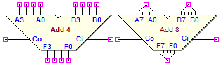
Adders (4-bits [Wire version], and 8 bits [Bus version], F = A + B, with Ci and Co):
Comparators(4-bits [Wire version], and 8 bits [Bus version]):

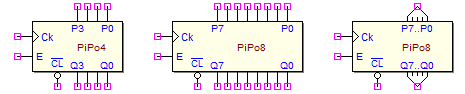
Parallel Registers (4-bits, 8-bits [Wire version], and 8-bits [Bus version]):
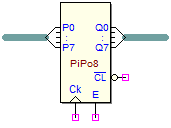
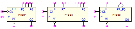
Parallel Input - Serial Output Registers (4-bits, 8-bits [Wire], and 8-bits [Bus]):
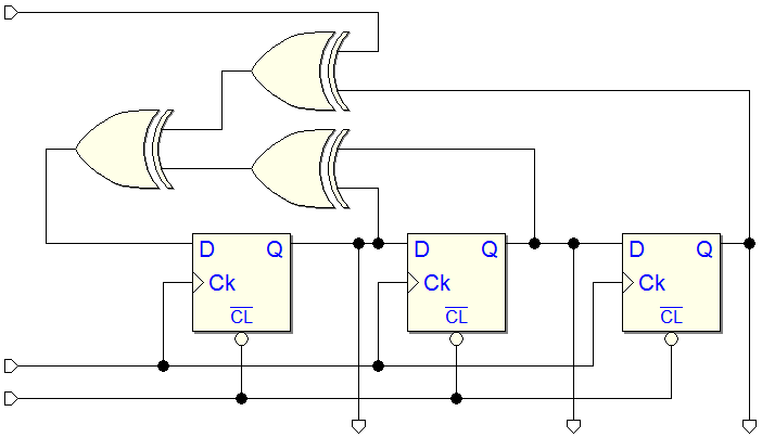
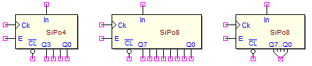
Serial Input - Parallel/Serial Output Registers (4-bits, 8-bits [Wire], and 8-bits [Bus]):
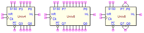
Universal Registers (4-bits, 8-bits [Wire], and 8-bits [Bus]):
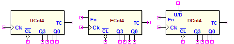
Simple Counters (4 bits, Up version, Up with Enable, Up/Down with Enable):
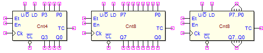
Universal Counters (4 and 8 bits, Up/Dn with Enable and Preset [Wire]; 8 bits [Bus]):
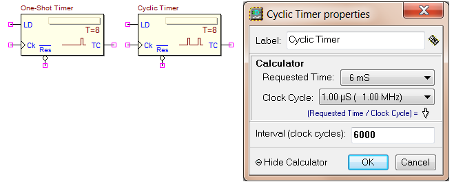
Timers, programmable with the "Cyclic Timer Properties" dialog:
Random Access Memories (RAM) (4 bits [Wire], and 8 bits [Bus]):
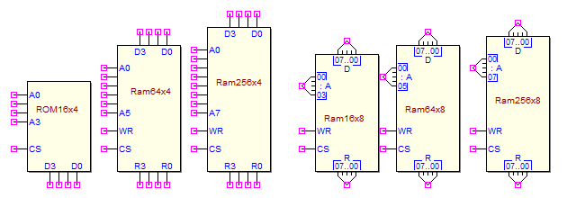
- Input Data [D3..D0] or [D7..D0] and Output Data [R3..R0] or [R7..R0] are separated;
- Asynchronous Read/Write, CS=1 to select, WR=1 to write (latches on pos. edge).
Read Only Memories (ROM) (4 bits [Wire], and 8 bits [Bus]):
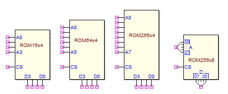
- Output Data [D3..D0] or [D7..D0], asynchronous Read, CS = 1 to select.
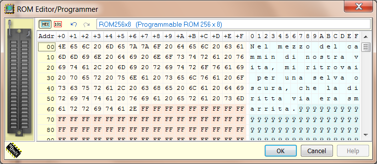
Using the ROM context menu, you can open theROM Editor/Programmer, to edit the memory content inBinary, Hexadecimal or ASCII format:
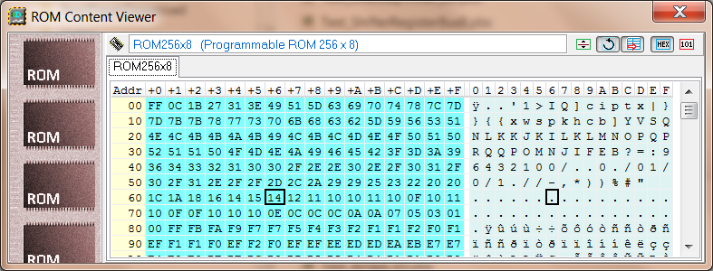
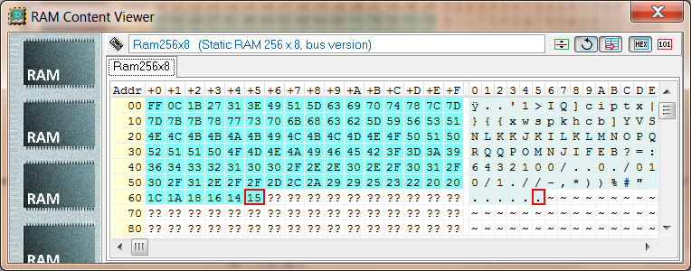
ROM and RAM contents can be observed during simulation, using the ROM and RAM Content Viewers. Below an example of both windows:
The "Component Info" command ![]() has been eliminated from the main menu: now, this information is always displayed on the status bar, when moving the mouse on the components.
has been eliminated from the main menu: now, this information is always displayed on the status bar, when moving the mouse on the components.
When inserting a component, you can rotate it with the mouse right button. A click longer than half second (or the<Escape> key) closes the command . However, it is always possible to rotate the component by pressing the key <R> during its placement, as in the previous versions.
Fixed a bug of initialization of Counters: now, after
the de-activation of Clear, the next Clock active edge is always correctly evaluated.
Deeds-DcS (Timing Diagram)
Fixed a Bug related to the caption, in the timing diagram, related to multiple input and output components. If, in the schematic editor, the user forgot to name a component, a critical error occurred in the timing diagram window ("Index Out of Bound"), when trying to open its sub-tracks.
In the Timing Diagram, the name of the current Test Sequence is now visible in a field at the bottom left of the window. A click on this field will activate the sequences menu, among which we find the new command "Set Default Sequence":
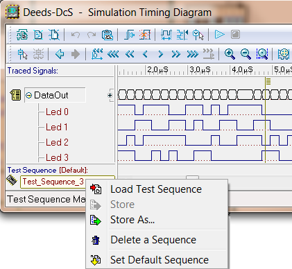
The "Default Test Sequence" will be automatically loaded in the timing diagram, when opened. The command "Set Default Sequence" opens a dialog box, where the current sequence is initially selected, but you can choose any sequence.
Above the name field of the current sequence, the string "[Default]" appears when the current sequence is also the defined "Default Test Sequence".
The default name of a new sequence, when saved, has been changes in "TestSequence1".
Now, in the Timing Diagram, a FSM main track reports the symbolic state names, instead of the state codes. If you wish to see the state codes, you need to expand the sub-tracks:

 Deeds-FsM
 A new dialog has been designed, to set inputs and outputs, state variables and the model of the FSM (Moore or Mealy). User can define these parameters when creating a new file (File/New command), or later on, during the construction of the state chart.
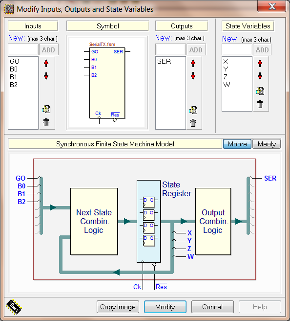
The "Copy Image" button saves on the clipboard the whole dialog window.
The Moore/Mealy option is set by default to Moore. The user is prompted to change model to Mealy, if trying to insert a Conditional Output in the chart.
Older files are automatically adapted to the corresponding model, depending on their content. If the current chart includes one or more Conditional Outputs, the user can't switch to the Moore model.
Following this update of the file contents, the "fsm" file version has changed but, as usual, older files are compatible with the new version (a new file is readable only by the new version).
Now, the Mouse Wheel controls the Zoom In/Out feature.
The Delete command, available before only as "shortcut", has been added to the "Edit" menu of the main window.
 Deeds-McE
![]() Now the directives "DB" e "DW" work correctly with negative numbers operands.
Now the directives "DB" e "DW" work correctly with negative numbers operands.
Deeds-DcS, Deeds-FsM, Deeds-McE
 A "local" demo file can't be overwritten or damaged by the user. In fact, every file that is located under the installation directory can't be saved there by Deeds. Use the "Save As" command to save the file in another place. Similarly, it is necessary to use "Save As" with a file that has been downloaded in the system Temporary Directory.
The browsers included with the previous versions of Deeds are not available in the current one. Their function are now executed by the default web browser installed in your system.