Deeds-DcS
 Reset Generator
A new component has been introduced, the "Reset Generator":
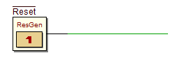
The new Reset Generator component generates a logical ‘0’ when the Simulation by Animation starts. After about 1.5 seconds its output returns to ‘1’. From now on the Reset Generator will behave as a push-button: when pressed generates ‘0’, when released generates ‘1’. Since a lot of sequential components use logical ’0’ to reset their state, it can be used to automatically reset the circuit at the beginning of the simulation.
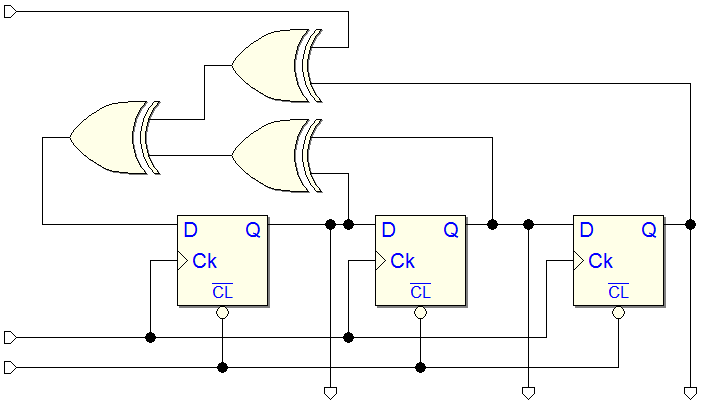
An example of use is shown in the next figure. At the beginning of the simulation (red arrow) a logical ‘0’ is generated, the circuit is forced to the reset state. In this phase, the Reset Generator changes color as if it is pressing itself. After about 1.5 seconds, the reset line goes to ‘1’ and the circuit starts to work (green arrow). From now on the circuit can be reset again, if necessary, by pressing the Reset Generator (blue arrow).

It is possible to assign a user label to the component. The label is placed like the other ones, outside the component box. The label can be edited, in a standard way, with the properties dialog. However, the generated signal is 'active low' and this setting cannot be changed. When inserting a new Reset Generator component, the label '!Reset' is assigned by default, to underline its function. There may be (even if it can make little sense) more than one Reset Generator for each circuit file.
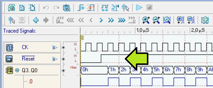
In the Timing Diagram, the Reset Generator behaves like a push-button, with the possibility of defining its progress over time. Pay attention, its initial value is always 'low', and that it is not editable. The subsequent transitions can be decided freely by the user, as is the case for all the other input tracks (see the green arrow, in the next figure).
The Reset Generator also works on FPGA. This means that it can be used to automatically generate a reset activation on our circuit even on a synthesis on a FPGA chip (provided that a button of the FPGA card has been associated to it). The Reset Generator, like the other input components, does not generate a specific VHDL component in the compiled network, when the user does not associate it with a physical push-button on the FPGA board in use (in the VHDL, a simple unconnected input is generated).
Memories with Tri-state data bus
ROMs and RAMs with Tri-state data lines have been introduced. These new components have been added to the library, they do not replace the previous ROMs and RAMs devices, which remain available there.
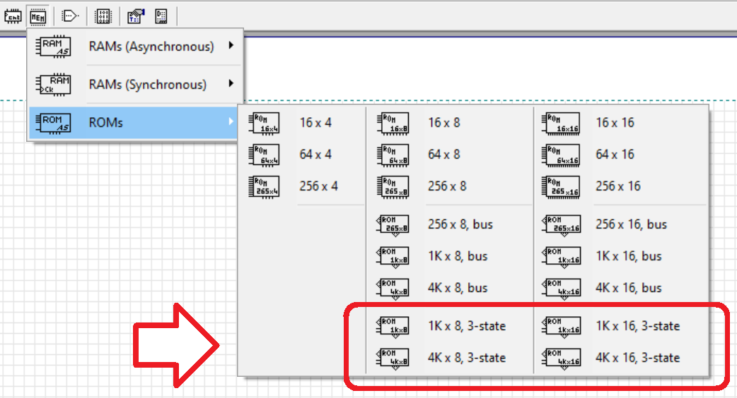
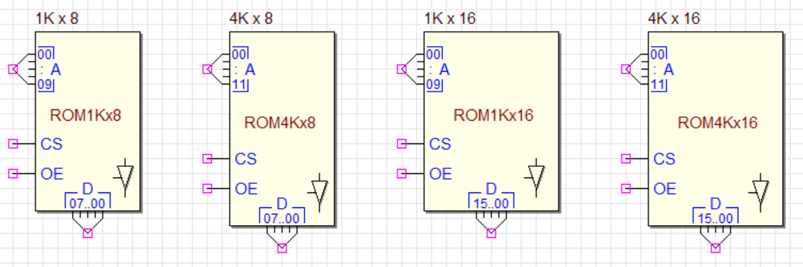
The new ROMs are asynchronous and show Tri-state data outputs. The available sizes are 1K x 8 bit, 4K x 8 bit, 1K x 16 bit and 4K x 16 bit:
Instead, the new RAMs are synchronous and show bidirectional Tri-state data lines. Available sizes are 1K x 8 bit, 4K x 8 bit, 16K x 8 bit, 1K x 16 bit, 4K x 16 bit, 16K x 16 bit:
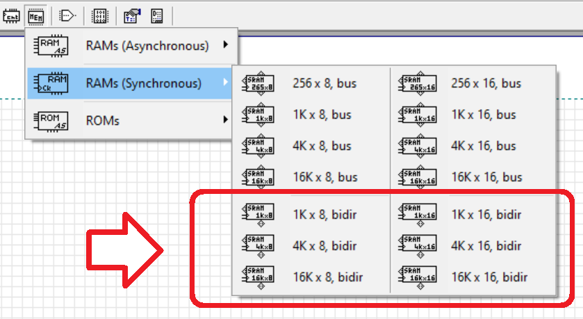
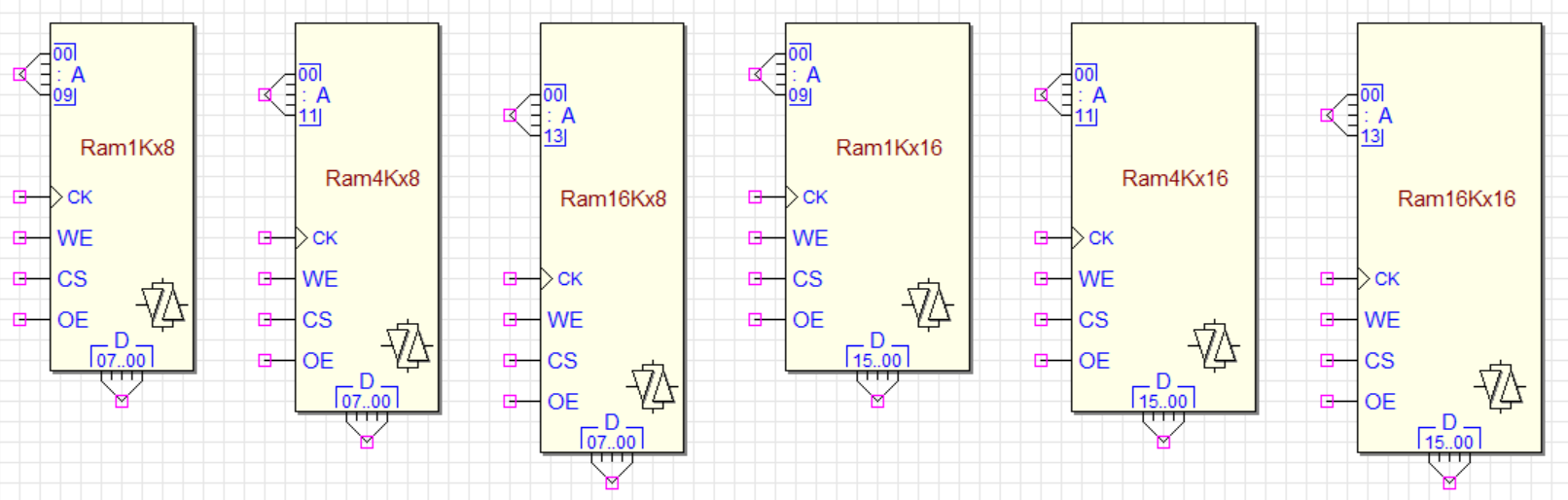
The Tri-state buffer icon, shown on the component symbol, helps to distinguish the new ROM and RAM components with the Tri-state data bus from those that have separate data inputs and outputs. For ROMs, close to the data bus connection, we display the icon of a Tri-state buffer. RAM symbols, similarly to ROMs, show a Bidirectional buffer.
The activity of the Tri-state buffers (for ROMs), and the Bidirectional one (for RAMs) are highlighted during the simulation (the icons of the Tri-state buffers, located next to the data bus connection, are coloured according to the component state).
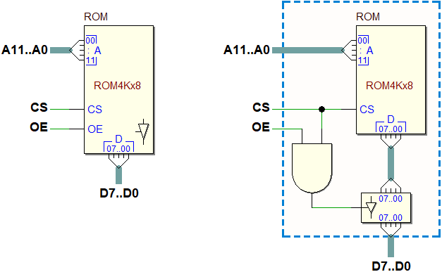
The next figure shows the logical functionality of the CS (Chip Select) and OE (Output Enable) of a ROM, described as an equivalent schematic using a ROM without Tri-state capability:
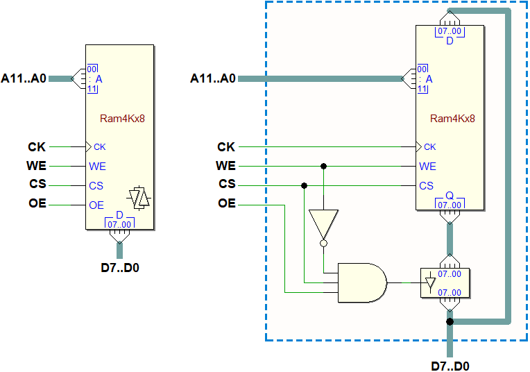
In the following figure, the logical functionality of the WE (Write Enable), CS (Chip Select) and OE (Output Enable) of a RAM is represented, using a RAM without Tri-state capability. Note that the activation of the WE input automatically disables the data output Tri-state buffers:
Note: the new memory components with Tri-state bus are regularly exported in VHDL code. Here an example of memory system built around a bidirectional bus (click to open it in the Deeds-DcS):

'.pbs' and '.cbe' file version
The internal file format of the '.pbs' and '.cbe' files has changed (version '1.034'). The change has been necessary because of the addition of new components. The old files are readable by the new Deeds version, while files created by the current version are not compatible with the older Deeds-DcS release.
Multiplexers
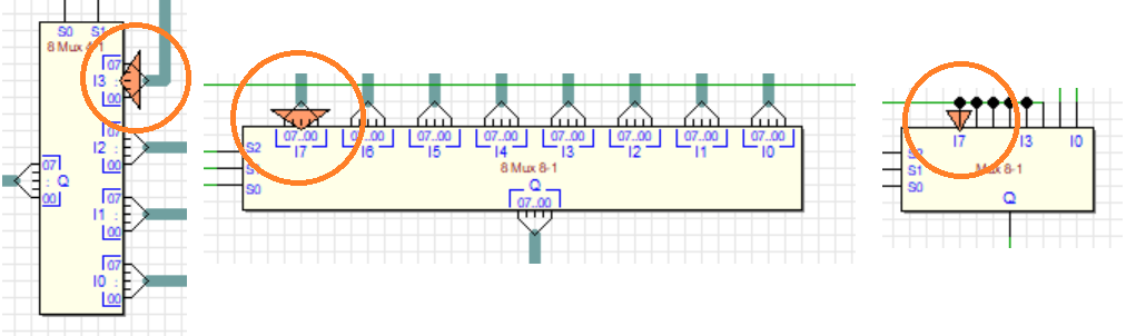
Now, during the simulations, multiplexers show the selected input line (or bus), helping the understanding of the network, especially in datapath schematic. The components have NOT changed, only their simulation aspect has been updated. In the examples of the next figure, the circles show the changes to the graphics. The selected input line (or bus) is highlighted with a coloured triangle.
Selection cursor
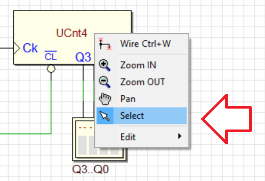
We also added the "Selection Cursor" to the context menu to return to the cursor's default mode.
Context Menu and Tool Bars
The Context Menu items and the upper Tool Bars has changed a bit. Now, during simulation, some commands are not only disabled, but also hidden, to simplify the interaction.
Tri-state Components (VHDL)
As suggested by Arkadi Poliakov, we modified the VHDL description of tri-state buffers, adapting them to the behavior expected in Deeds, i.e. also taking into account unknown inputs.
Load DMC8 Project command
A few minor problems have been fixed, regarding the Load DMC8 Project command (see the next figure).
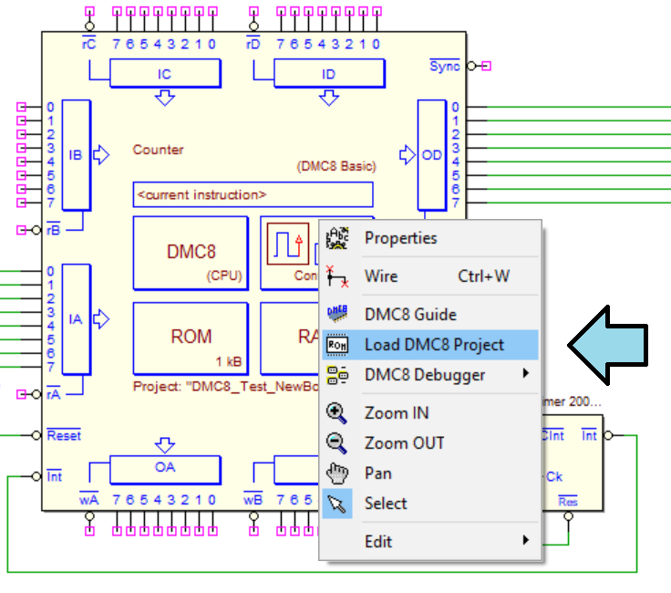
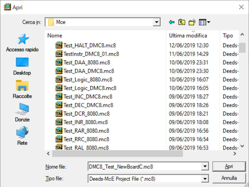
Now, the dialog that allows to choose the project file '.mc8' to be loaded into the microcomputer components, opens correctly the last directory previously used.
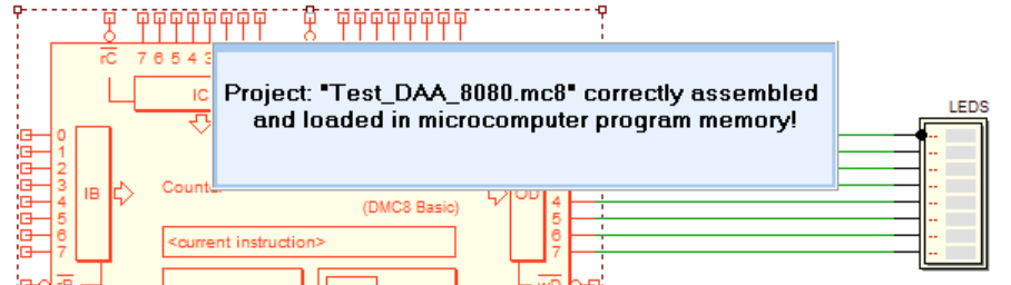
Moreover, message generation related to '.mc8' project loading has been corrected. Previously, even if the file was not loaded correctly, under certain conditions the panel indicating the success of the operation was displayed anyway.
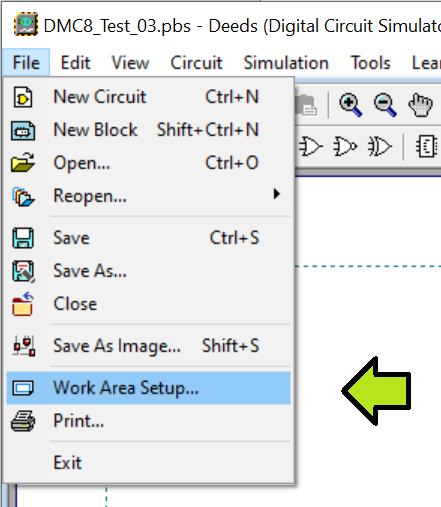
Work Area
Now, while simulation is active, the Work Area Setup command is correctly grayed (the command allows you to define the size of the drawing sheet of the schematic).
 Deeds-McE
 Code Editor commands
The short cut <Shift>+<Ctrl>+<Ins> was not handled and therefore this command did not result in saving UNDO information. The bug has been solved by adding this short cut to the Paste command, together with the usual short cuts <Shift>+<Ins> and <Ctrl>+V.
A similar problem has been fixed for other key combinations, avoiding unwanted behavior.
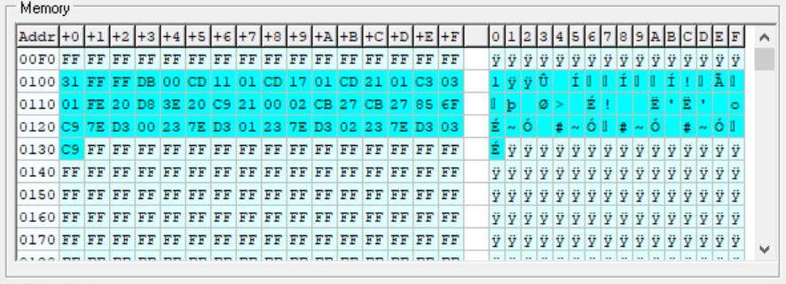
Emulation Run Mode
During the RUN Mode, when one paused the emulation, the memory display window was not updated. Now the problem has been solved.