Version Notes
(Ver. 2.10.300 - Jan 19, 2018)
 Deeds-DcS (Editor)
 File Version
Changed the internal version of the “.pbs” and “.cbe” file format (now: 1.030). The change was necessary to support some new parameters and the addition of new components. Pay attention that the old files are readable by the new version, while files created by the current version are not compatible with the older ones.
New Limits
Increased the limits of the simulator, brought to the following maximum values:
- 65535 components;
- 4095 inputs;
- 16383 outputs;
- 1023 CBE blocks;
- 1024 pins for a CBE;
- 256 wires for a bus.
Circuit Block Elements (CBE)
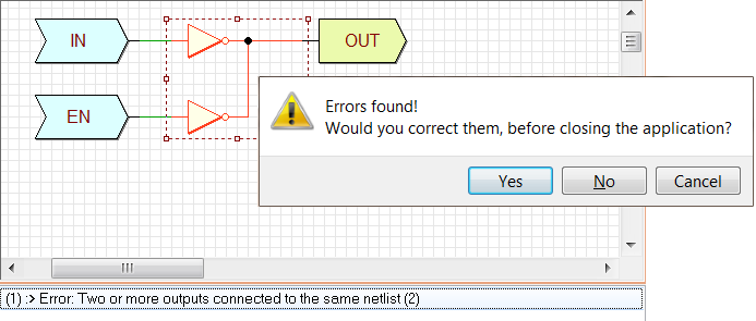
Due to a bug, in the previous version no error checking was performed on a CBE component when under construction in the Deeds-DcS. If a CBE contained a connection error, the problem only appeared during the simulation. Here an example of connection error:
The error was displayed as if it were present in the main network, instead inside the CBE component:
With the current version, the error checking is correctly performed when saving or closing the CBE under construction. If fatal errors are there, the user is asked to correct them and, in any case, the presence of one or more errors is stored in the CBE file itself:
When we try to load a CBE component into a schematic, the presence of errors is checked in advance, and the erroneous component is not accepted, in a way similar to what already happens for FSM components:
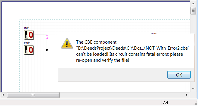
If problems occur in the simulation of files containing CBE components created with the previous version, we recommend to reopen the CBE files and save again it. It will be checked, in order to highlight the presence of any formal error. Then, you can replace/insert the corrected CBE components in your schematic.
Memories
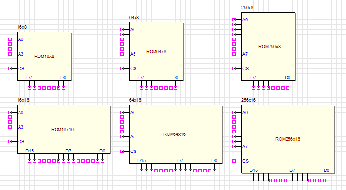
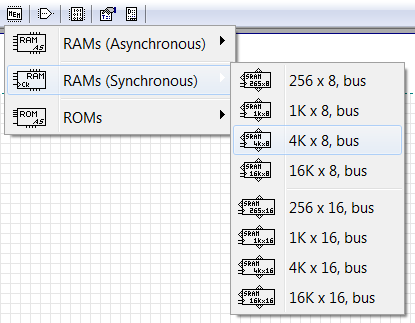
The following asynchronous ROM memory components have been added to the library (16, 64 or 256 locations per 8 bits, and 16, 64 or 256 locations per 16 bits):
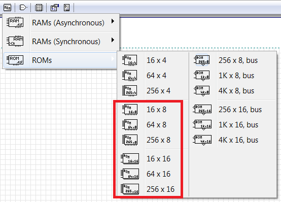
We have structured the ROM menu differently (highlighted in red the new components):
We have also changed the RAM memory component menu (without adding new components):
Fixed a bug regarding the ROM 1K x 16: now the address bus pin show the correct number of wires and can be connected as expected.
ROM Editor/Programmer
The format of the ".drs" files has been now explicitly documented. These files are used to save and load the contents of a ROM (through the ROM Editor/Programmer dialog, shown in the next figure):
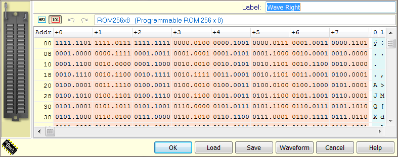
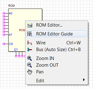
The documentation on the ROM Editor/Programmer dialog and the ".drs" file format can be read here. The same page is available by clicking on the help button of the dialog, or on context menu of the ROMs:
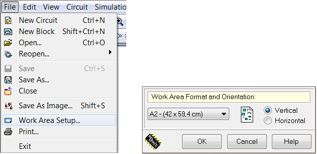
Work Area extended
Now, also the A2 sheets are supported, in the circuit editor. Note that the menu command has changed in "Work Area Setup" (instead of "Paper setup"), and the dialog has been re-styled a bit:
Component Selection
We have changed a bit the behavior of mouse pointing when selecting components. Now the mouse icon, when no command is active, depends on whether or not the mouse pointer passes over one only or a multiple selection of components.
If there is no selection and no component under the mouse pointer, its shape is the default:

otherwise, over a not-selected component, it is:

Note that the Backdrop component makes an exception, because this mouse pointer shape is visible only passing close to its border, indicating that a click inside it will not be effective to select it. The change in the selection mode of the Backdrop component was necessary because it was too easy to click inadvertently on the Backdrop background instead of on a component. Now the Backdrop is selected only if we click on its edge (less than one grid step). Once selected, however, the click to drag it can be done anywhere on its surface, except to click on anyone of the contained component.
If there is one only component selected, when the pointer mouse passes over it, the shape is:

just to suggest the possibility of moving the component elsewhere. If a multiple selection is there, the shape displayed is:

If we are in Simulation by Animation, or if there is active the Timing Diagram window, instead, the cursor remains always with the default shape.
Undo shortcut
To perform an Undo, in addition to the menu command and its shortcut "Alt + BkSp", now you can also press the classic "Ctrl + Z".
Schematic Only upgraded
When generating an image through the appropriate Save Circuit Image dialog, or with the Edit/Copy Image command, if you select the Schematic Only option, the wires will be drawn black, to grant a better contrast. See the next figure to compare the two drawing mode:
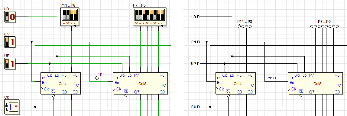
Outline Only
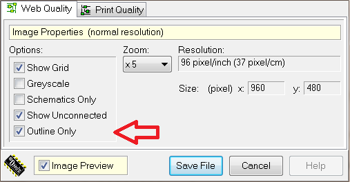
The Options/Graphic Options/Flag Graphics Style menu item has been renamed as Options/Graphic Options/Outline Only Style. Now this parameter can be defined independently in the Save Circuit Image dialog, using the new Outline Only option:
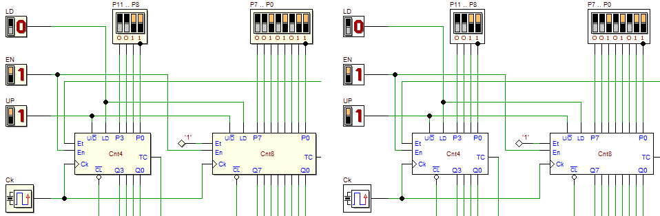
In the next figure the two graphic options are compared (Outline Only is ON for the right side image):
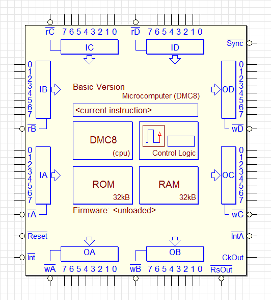
New DMC8 Components
The previous DMC8 Microcomputer component has been substituted by the DMC8 Basic Microcomputer. The new component is equivalent to the previous one, but is more versatile and definable (see later in this document):
A new version of the same microcomputer has been introduced in the present version, the DMC8 Enhanced Microcomputer, that implements a vectorized interrupt system and doubles the number of available input and output ports:
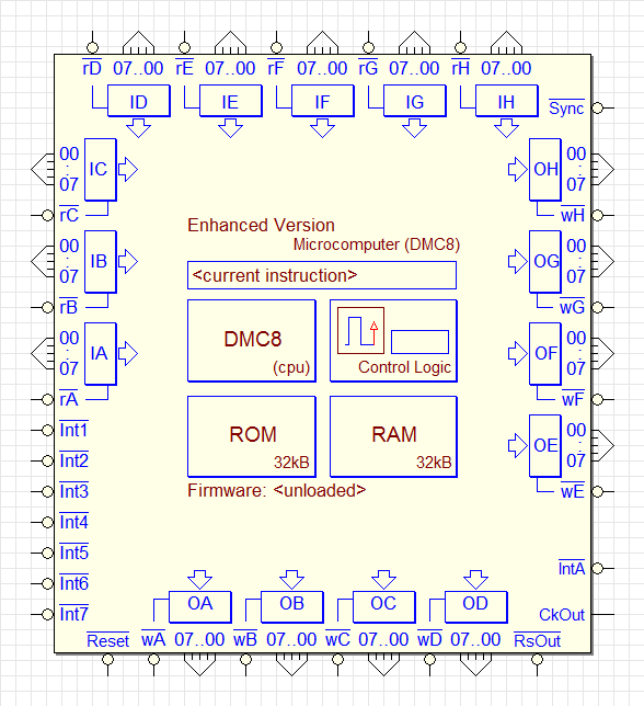
Note that the port connections, for reasons of space, are of "bus type"; moreover, note the seven interrupt lines, on the left side of the symbol.
Both the systems can be programmed either as a DMC8 (Z80-like) core or a D8080 (I8080-like) core, and both have ROM and RAM memory size that can be defined by the user. All these information are contained in the project file (".mc8") that can be loaded into the component.
After loading the project file, on the symbol will appear the name of the core (DMC8 or D8080), the amount of ROM and RAM memory (from 1K to 32K) and the model of the microcomputer ("Basic" or "Enhanced"). Since the file loaded into the component is no longer just only a source program, but contains also setup information, the context menu items have been modified, highlighting the fact that now a "project file" is loaded:
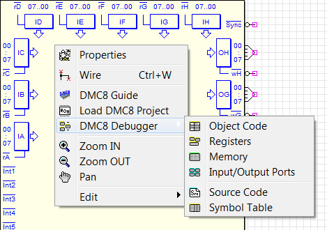
The DMC8 systems guide has been upgraded, and it is available using the component context menu (see the figure above). You can read the guide also with a click here. Moreover, the debugger windows also have been upgraded to the new features.
BUG fixes
Fixed a bug relative to the default size of BackDrop components, when inserted into the schematic: previously, the horizontal dimension did not respect the placement on the drawing grid. Now, when inserting a component, while the label dialog is opened, the component symbol is no longer affected by an annoying double drawing of the component above it.
When executing a File/Close command with a CBE in the editor, the Symbol Editor was opened: now no longer. In any case, the user can re-open the Symbol Editor when needed (with the command View/Show Symbol Editor or the shortcut "F7").
In the operation of inserting an FSM component, now its symbol is correctly displayed in the preview of the file opening dialog, even if the file is labeled as "incomplete or wrong". In addition, some error messages related to the loading of FSM files have been corrected and made more complete.
The installer did not defined the association between the ".cbe" extension and the Deeds-DcS. Now, the problem has been corrected.
Fixed a bug regarding the DMC8 object code window, during the simulation. Turning the simulation mode to step-by-step, in spite of the correct simulation, in the object code window, the current instruction highlighting was not updating, during the program execution (and the internal register window too).
Deeds-DcS (FPGA support)
Added FPGA boards
Support has been added for two small and inexpensive FPGA boards, based on the Cyclone II "EP2C5T144C8N" and Altera Cyclone IV "EP4CE6E22C8N" chips:
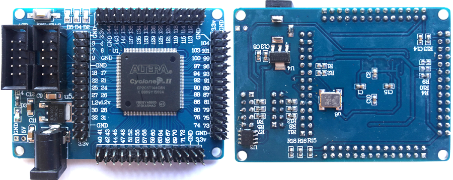
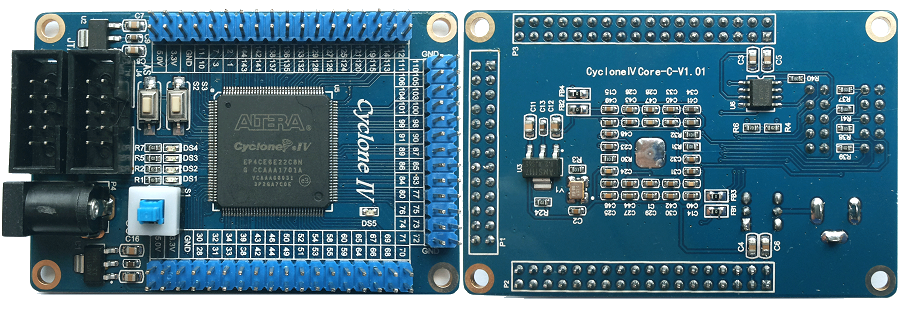
These boards are characterized by a very limited number of input/output devices, and they need to be connected to LED, switches and so on with the active participation by the students.
Moreover, in the absence of switches, push-buttons and LEDs in appropriate numbers, some functions such as Slow Clock and related controls must be controlled via the headers (visible in the previous photos), to which they will be connected, by the user, to appropriate switches, push-buttons etc.
A list of the complete support for FPGA Boards is visible in the next figure, where the “Test on FPGA” dialog is shown:
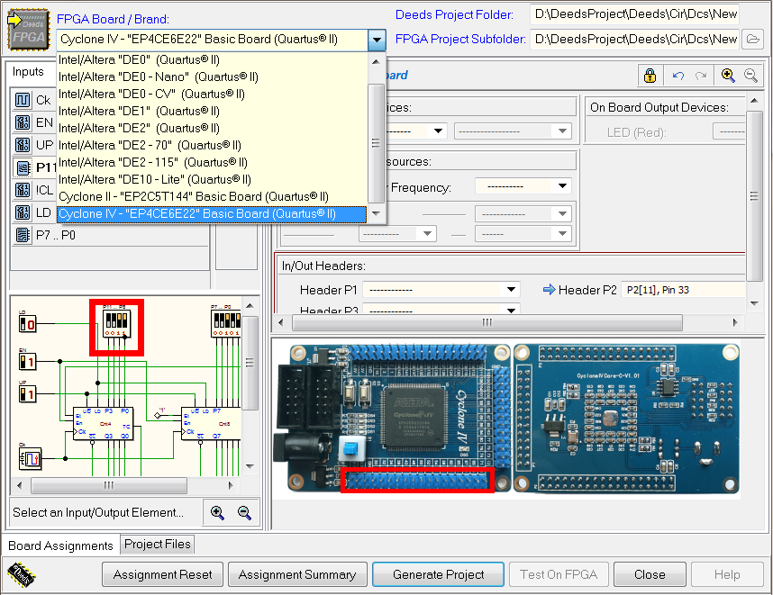
A command has been added for the deletion of all "associations" relating to a particular FPGA board. The command is available via the Assignment Reset button, as shown in the figure above. Note that a few FPGA pins are not usable because reserved, or already connected on the board. For this reason, a certain number of pins, although available on the headers, are not included in the drop-down lists in the dialog.
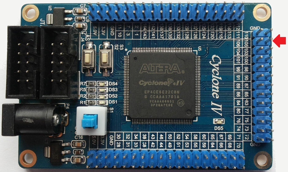
The FPGA pin names appear printed on the cards, close to the headers. For this reason, the pin indexes of the headers, in the drop down lists, are completed with the pin numbers of the chips (for user reference, because easily readable on the boards). See the figure below:
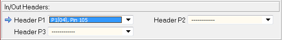
In this example, we read in the field of the drop-down list box: "P1[04], Pin 105". This means: "Header = P1", "Header pin index = 04" and "FPGA Pin number = 105". The pin is easily visible on the board, as pointed by the red arrow below:
BUG fixes
Fixed a bug for which the saving of the vertical split position in the Test on FPGA Dialog did not work.
The Assignment Summary window did not correctly update when the type of card was changed. Now the window and its table are re-initialized and displayed correctly.
Deeds-DcS (Timing Diagram)
Vertical Enlarge/Reduce commands
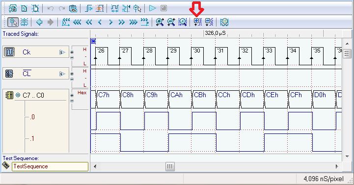
Two commands have been added, in the timing command bar, to enlarge or reduce all tracks vertically. The vertical magnification is useful for high resolution screens. The figure below shows where they are placed and the default vertical dimension of the tracks:
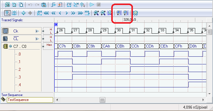
The next figure shows the effect of the vertical enlarge command (the button highlighted in red):
BUG fixes
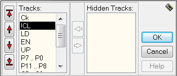
Fixed a bug in the Track Handling Dialog: the tracks with negated name were listed without the negation. Here an example of track listing in the dialog, were the input !CL is represented correctly with the "!" operator in front of it.
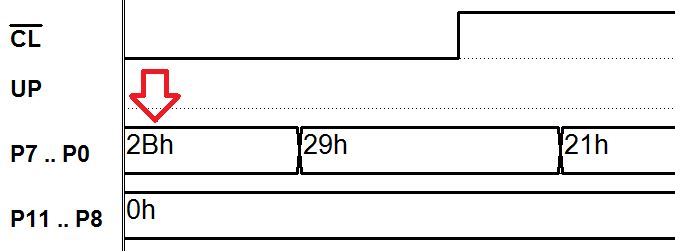
Fixed a bug for which the string with the initial value of an multi-wire input component was not drawn inside the trace, when the diagram was saved as high-quality image. Here an example of correct drawing:
 Deeds-McE
Now the Deeds-McE also supports the D8080 instruction set (Deeds version of the well-known Intel 8080). Moreover, the core of the DMC8 has been upgraded; now it supports vectorized interrupts (thanks to Luis Claudio Gamboa Lopes for the support provided to the whole operation).
Two different versions of the “DMC8 Microcomputer” are now available: the "DMC8 Basic", that is similar and compatible with the previous one, and the "DMC8 Enhanced", with a greater number of I/O parallel ports and a vectorized interrupt system.
We updated the microcomputer online documentation, now including the D8080 instruction tables: the guide is available here.
More over, the source code editor has been enhanced, with multi-level undo/redo capability, and better source highlighting.
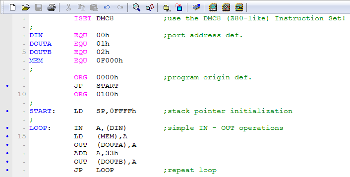
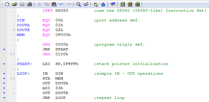
The new ISET directive allows to choose the instruction set in use. In the source code, it must be inserted before any other directive or instruction, but it can be preceded by comments. Note that it must be entered only once in the source code.
In the current version, you can choose between the native instruction set of the DMC8 (Z80-like, reduced) and the instruction set of the D8080 (I8080-like, complete). In the next two figures, two examples of the same program are shown. The first one is written in DMC8 code, and in D8080 code the second:
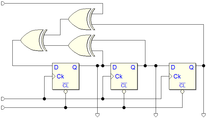
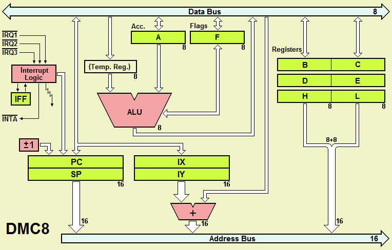
This is the functional block diagram of the DMC8 processor data-path, which shows the presence of the three new interrupt inputs !IRQ1, !IRQ2 and !IRQ3, on the left side of the figure:
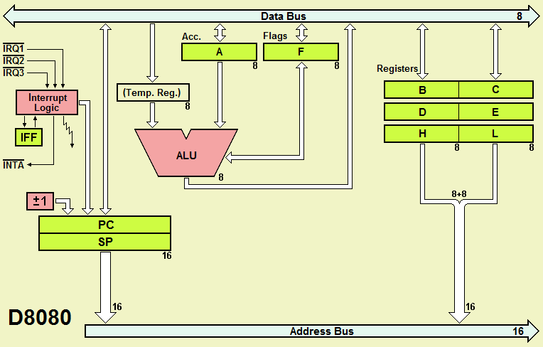
Below, instead, the D8080 (as you can see, it is a subset of the DMC8):
 Vectorized Interrupt
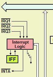
Starting from the current version, the DMC8 core supports a seven levels vectorized interrupt system. The new core has three interrupt request inputs, active low (!IRQ3, !IRQ2 and !IRQ1):
When these lines are all high, the processor receives no interrupt request; otherwise, if one or more line is activated and interrupts are enabled, the processor is interrupted, and the corresponding interrupt handler is executed, according to the following table:
!IRQ3 |
!IRQ2 |
!IRQ1 |
Int. Request |
Address |
1 |
1 |
1 |
No Interrupt |
- |
1 |
1 |
0 |
Int. 1 |
0008h |
1 |
0 |
1 |
Int. 2 |
0010h |
1 |
0 |
0 |
Int. 3 |
0018h |
0 |
1 |
1 |
Int. 4 |
0020h |
0 |
1 |
0 |
Int. 5 |
0028h |
0 |
0 |
1 |
Int. 6 |
0030h |
0 |
0 |
0 |
Int. 7 |
0038h |
The system is compatible with the previous one, with no vectorized interrupts, if we use the highest priority request only. As the next figure shows, in the simplest "DMC8 Basic" system (equivalent to the one of the previous versions), the three inputs are connected together. In this way, the activation of the !Int line launches of the routine starting at the address 0038h:
Note that, when an old project is opened in the current version, the previous microcomputer component is automatically substituted with the new equivalent "DMC8 Basic" version. In the "DMC8 Enhanced" system, instead, the three inputs are internally connected to a priority encoder, which handles the seven interrupt request lines !Int7, !Int6, .. !Int0 (see the figure below):
!Int7 has the highest priority. The activation at the same time of several requests executes the code of the one with the highest , according to the following table. Requests with lower priority will be considered when the requests with higher priority requests will be deactivated:
!Int7 |
!Int6 |
!Int5 |
!Int4 |
!Int3 |
!Int2 |
!Int1 |
!IRQ3 |
!IRQ2 |
!IRQ1 |
Int. Request |
Address |
1 |
1 |
1 |
1 |
1 |
1 |
1 |
1 |
1 |
1 |
No Interrupt |
- |
1 |
1 |
1 |
1 |
1 |
1 |
0 |
1 |
1 |
0 |
Int. 1 |
0008h |
1 |
1 |
1 |
1 |
1 |
0 |
- |
1 |
0 |
1 |
Int. 2 |
0010h |
1 |
1 |
1 |
1 |
0 |
- |
- |
1 |
0 |
0 |
Int. 3 |
0018h |
1 |
1 |
1 |
0 |
- |
- |
- |
0 |
1 |
1 |
Int. 4 |
0020h |
1 |
1 |
0 |
- |
- |
- |
- |
0 |
1 |
0 |
Int. 5 |
0028h |
1 |
0 |
- |
- |
- |
- |
- |
0 |
0 |
1 |
Int. 6 |
0030h |
0 |
- |
- |
- |
- |
- |
- |
0 |
0 |
0 |
Int. 7 |
0038h |
The "Enhanced" version, as shown in the figure, has 8 parallel input and 8 parallel output ports (described later). Both versions can be indifferently programmed as DMC8 or D8080 systems.
Input and Output ports
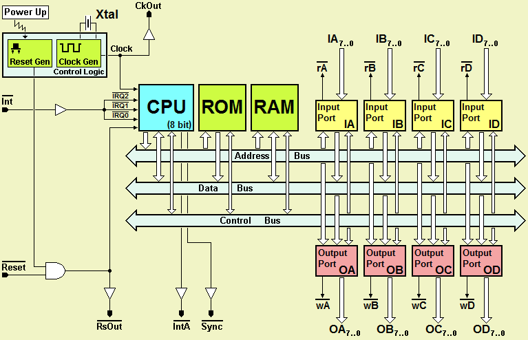
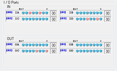
As already written, the "DMC8 Basic" system is equivalent to that of previous versions, and it has 4 input ports (IA, IB, IC and ID) and 4 output ports (OA, OB, OC and OD), so the Deeds-DcS circuital symbol is very similar to that of the previous version:
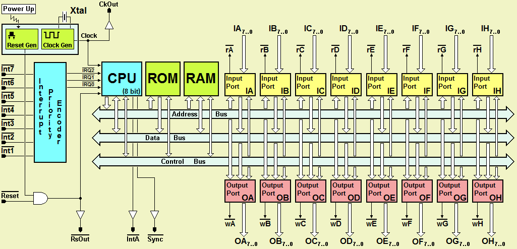
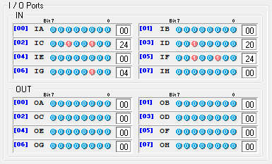
The "DMC8 enhanced", instead, incorporates 8 input ports and 8 output ports, for a total of 64 input and 64 output lines; here the Deeds-DcS circuital symbol:
Project definition
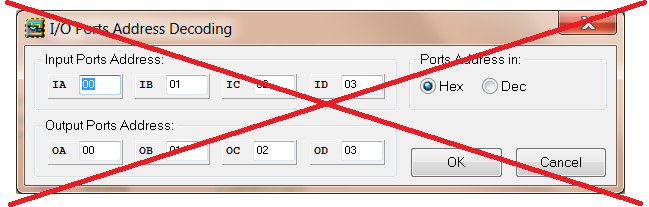
In the new version, the I/O Ports Address Decoding Dialog is no longer there. This dialog allowed only to define the addresses of the ports:
Previously, the main page was organized around three pages ("Board", "Editor" and "Debugger"):
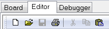
The "Board" page has been removed:
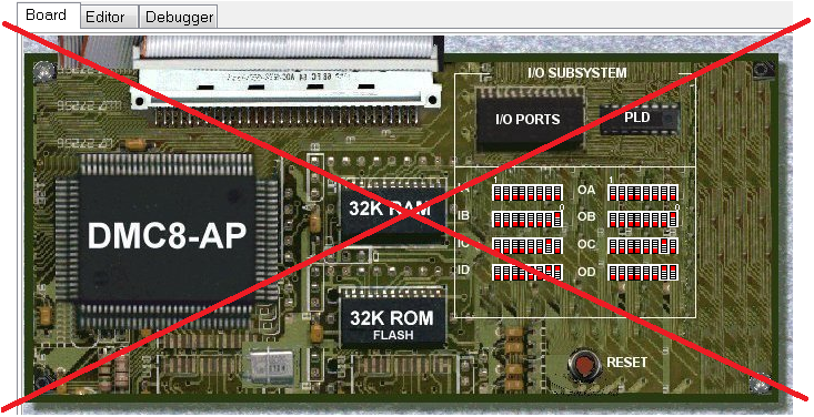
We replaced the "Board" page with the new "System" page:
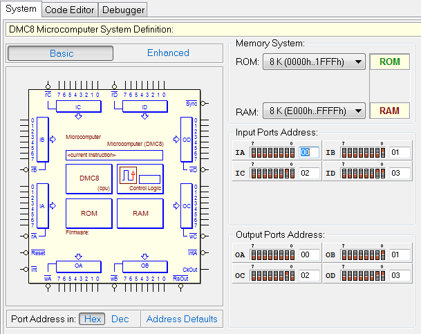
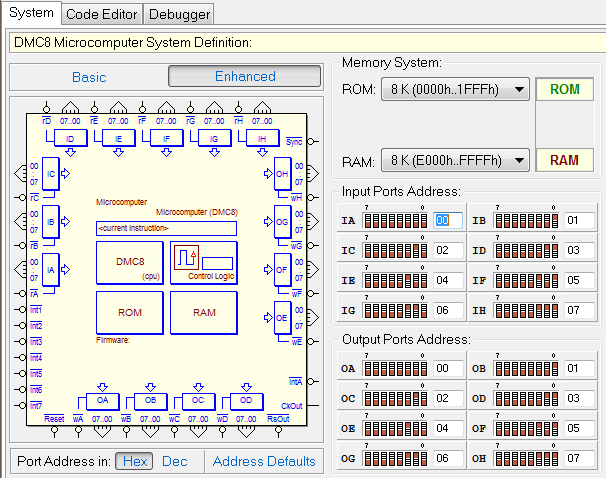
Microcomputer System Definition
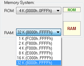
In the new "System" definition page, the user can choose which of the two systems will be used in the project ("Basic" or "Enhanced"), the size of the ROM and RAM, and the port addresses. In the next figure the "DMC8 Basic" version is selected:
In the following figure, instead, the "DMC8 Enhanced" version has been chosen:
Memory Size Definition
Starting from the current version, both the microcomputer versions allow to be configured with different ROM and RAM memory sizes. In this way, it is possible to scale the size of the system to the effective needs of the project. It is possible, using this feature, to load the microcomputer system on a small FPGA chip, or to load two or more on a larger chip.
The user can setup the memory sizes in the specific pane:
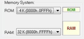
The dimension of the ROM can be defined from 1 to 32 Kbytes, as in the following figure, starting from 0000h:
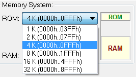
The dimension of the RAM can also range from 1 to 32 Kbytes; however, note that the ending RAM address is fixed (FFFFh):
At the compilation time, the assembler will control that the generated object code do not exceed the maximum available address, according to the size of the ROM and the configuration of the system. In case, the following message could be generated:
"Memory Error [nnn]: ROM memory upper limit exceeded!"
Run-time memory management has been improved as well, signaling reading or writing operations in "non-existent" locations, in addition to the previous existing checking of the attempt to write in ROM.
I/O Ports Address Definition
I/O Ports Addresses are editable both in binary, by clicking on the switches, or writing the address directly in the number field. In the next figure is visible the I/O Ports pane, showing the default addresses for a "DMC8 Enhanced" system:
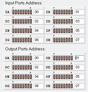
Note that the user can choose if writing the address in Decimal or Hexadecimal code, and also re-assign the default addresses:

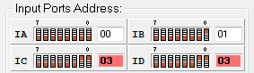
The addresses are verified while the user edits them. Input Port Addresses must be unique, as well as those of the Output Ports. If addresses are duplicated, the editing fields are colored, as in the following example:
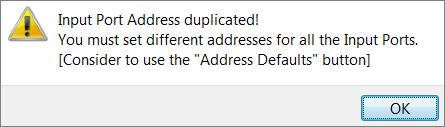
Please note that the user can’t exit the definition page until the addresses are adjusted (the consistency of the addresses is checked on changing the page, closing the application, opening a file, or creating a new one). If a duplication is found, the user is prompted with a message like the following one:
In any case, the user can always assign the default addresses, as seen before. When the system setup is changed, it is invalidated any previous compilation of the program, in order to update the emulation parameters and the debugger page.
Debugger Changes
Debugger Bar
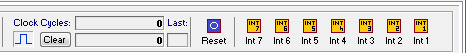
Depending on the system selected, in the Deeds-McE debugger page, only one (or seven) interrupt buttons will be visible. The next two figure shows the debugger header, respectively for the "Basic" and the "Enhanced" systems:


In the debugger, during the emulation operations, the user activates an interrupt request by pressing the corresponding button. The interrupt buttons will remain "lowered" until the corresponding interrupt request has been accepted (as if there were a hardware circuit capable of handling recognition and priorities of interruptions).
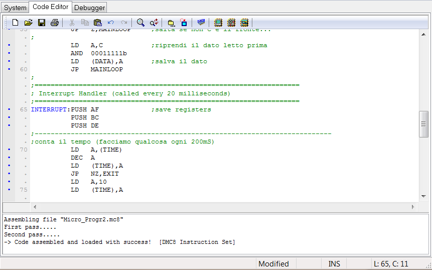
Registers pane
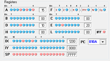
The contents of the Registers pane change according to the chosen processor core. Here the registers in the case of the DMC8 core:
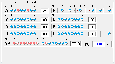
In the next figure, instead, when the core in use is the D8080 (the IX and IY registers have been hidden):
I/O Ports pane
The I/O Ports pane, for a "DMC8 Basic", will show the eight available ports in that microcomputer version (IA, IB, IC, ID, OA, OB, OC and OD):
Instead, for a "DMC8 Enhanced", the ports are sixteen:
Memory pane
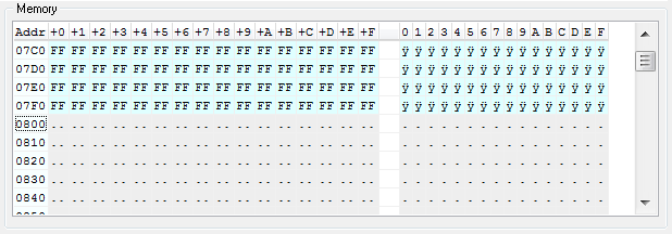
Since we can have areas of memory space "not-allocated", the appearance of the memory location now distinguishes the different zones. In the next figure, an example of display of the end of the ROM, followed by the not-allocated area:
Furthermore, we have improved also the highlighting of RAM memory, allowing to distinguish the locations written by different actors. Indeed, the emulator now internally distinguishes the memory locations in a higher number of categories than before:
- "Free Space" (no allocated memory for that address),
- "Unknown" (not- initialized memory location),
- "Instruction" (compiled instruction codes),
- "Program Defined" (locations defined by DB or DW directives),
- "RunTime Defined" (locations written by the program execution) and
- "User Defined" (location written directly by the user, by hand).
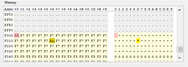
In the example below, we see the end of the “not-allocated” area and the first locations of RAM, where we can distinguish the F000h location (written by the program execution), and F016h cell, edited manually by the user:
To minimize the use of scroll bars, which can be rather cumbersome and inconvenient, I modified the memory context menu, which now allows you to move the view of the memory in increments of 256 locations:
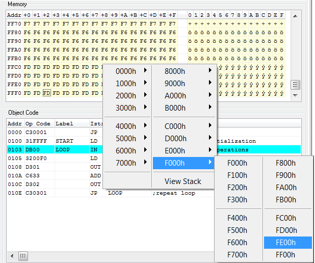
I have modified also the View Stack command (visible in the menu above), which moves the memory view to the locations currently pointed to by the Stack Pointer.
File/New Command
When the user clicks on the File/New menu command, a new project including the system default definitions is created, opening an empty file in the code editor. The default configuration defines the microcomputer system "DMC8 Enhanced", with 8 KByte of ROM and 8 Kbyte of RAM, and the port addresses defined as in the next figure:
The configuration can be edited by the user in any time.
Instruction Set
The following instructions (Z80-like) have been added to the DMC8 instruction set:
DAA
EX DE,HL
EX (SP),HL
Also the corresponding instructions (I8080-like) in the D8080 instruction set are now available:
DAA
XCHG
XTHL
Code Editor
The source code editor has been completely revised. Now it has multi-level undo/redo capability, that covers all commands, including Cut/Copy/Paste:

The code highlighting function has been improved and made fully compatible with the undo/redo system.
On the left side of the editor, now there is a column displaying the code line numbers:
Revised also the editor's Find and Replace commands, making them more usable, including the Replace All option.
The command "Ctrl + Up/Down arrows" has been added: it shifts all the text Up or Down, moving also the position of the cursor so that it remain visible in the window. Now, also the mouse wheel facility is supported. In the Options menu there is now an Editor Font Size command, which allows to define the size of the editor font:
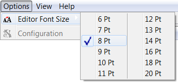
This command is especially useful using a video projector, to make more readable by the students the source code in the editor.
Code Markers and Breakpoints
Improved the column, on the left side of the editor, used
- to define the code breakpoints;
- to highlight the lines containing errors;
- to mark the code lines that generated executable code after the assembling.
- a blue ball (marks a line of executable code);
- a red square (marks a line of code with a breakpoint);
- a red arrow (marks a line with an error).
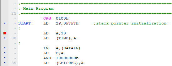
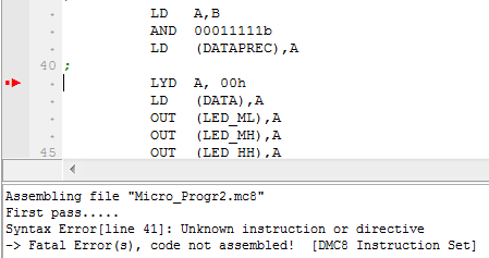
In the example above, the column shows that the comment lines do not generate code (they have not been marked), that the user has set a breakpoint on line 29, containing executable code, as line 27, 30, 32...
In the following example, line 41 contains a syntax error, and it has been marked with a red arrow (after the code compilation):
A Hint Message, moving the mouse over the column, remembers to the user that a code breakpoint can be defined (with a mouse click):
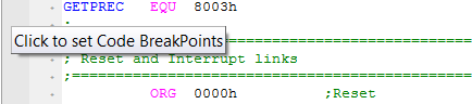
Note that, if the code has not yet been compiled or has been compiled with errors, the column does not accept clicks and the hint messages will not appear.
Breakpoints can be set also in the debugger, they will be updated also in the editor, and vice-versa.
New ".MC8" file version
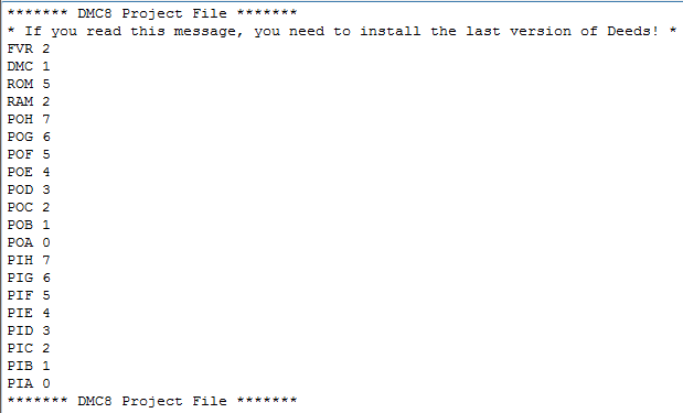
The internal format of the ".mc8" files has changed. The file contains not only the source code in assembly, but also the project setting information, coded in a header saved before the source code. A ".mc8" file should be now intended as a Project File, rather than a simple source file.
So, the menus have been modified so that the various items refer to Project Load and Save, and not simply to a source code file. The content of the file, including the header, is in text format, so it can be read by a normal text editor, even if it is strongly discouraged to edit the header manually. Here a file ".mc8" opened in a normal text editor, showing the file header:
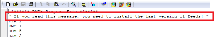
Note that, using a previous version of the Deeds-McE tool, opening a ".mc8" file in the new format, a message will appear in the text editor, stating that you need to install the latest version of the Deeds:
Anyway, the older header format is correctly read by the current version and, saving an old file, the header will be replaced, saved in the new format.
BUG fixes
The column / row coordinates, displayed on the right side of the Status Bar, now take into account the presence of the Tab characters in the program text, so that the position (Line, Column) of the cursor is displayed correctly:

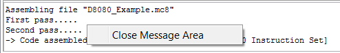
Compiling the file, messages are always displayed of the bottom message window, whether the result is correct or if errors are found. Now the context menu of the message window also allows to close it:
In the debugger, when pressing the Reset button, now the interrupt requests are deactivated as expected, together with the interrupt buttons that, if on, are switched off: